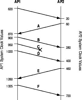
A primary function of CP is to measure network delay and detect packet loss along the cluster-to-cluster data path. Figure 5, Table 1, and Table 2 together illustrate how information in the CP header is used to make these measurements.
Each packet passing from one AP to another has several numbers inserted into its CP header. The first is a sequence number that increases monotonically for every packet sent. A remote AP may use this number to observe gaps (and reorderings) in the aggregate flow of cluster application packets that it receives. In this way, it can detect losses and infer congestion. In our example, AP2 detects the loss of packet C when the sequence number received skips from 14 (packet A) to 16 (packet D).
In addition, a timestamp is sent along with the sequence number indicating the time at which the AP sent the packet. The remote AP will then echo the timestamp of the last sequence number received by placing the value in the CP header of the next packet traveling on the reverse path back to the sending AP. Along with this timestamp, a delay value will also be given indicating the length of time between the arrival of the sequence number at the AP and the time the AP transmitted the echo.
By noting the time when a packet is received (![]() ), the AP can calculate the round trip time
as
), the AP can calculate the round trip time
as
![]() . In our example, AP2 receives packet B at time 280. The CP header
contains the timestamp echo 60 and an echo delay value of 30. Thus, the round trip time is calculated
as
. In our example, AP2 receives packet B at time 280. The CP header
contains the timestamp echo 60 and an echo delay value of 30. Thus, the round trip time is calculated
as
![]() . A weighted average of these round trip time calculations is used to
dampen the effects of burstiness.
. A weighted average of these round trip time calculations is used to
dampen the effects of burstiness.
|
Note that because sequence numbers in the CP header do not have any transport-level function, CP can use whatever C-to-C application packet is being transmitted next to carry this information. Since the packets of multiple flows are available for this purpose, this mechanism can be used for fine-grained detection of network conditions along the cluster-to-cluster data path.
We also observe that there is no one-to-one correspondence between timestamps sent and timestamps echoed between APs. It may be the case that more than one packet is received by a remote AP before a packet traveling along the opposite path is available to echo the most current timestamp. The AP simply makes use of available packets in a best effort manner. In Figure 5 this can be seen as AP2 receives both packets B and D before packet E is available to send on the return path. Likewise, an AP may echo the same timestamp more than once if no new CP packet arrives with a new timestamp. In our example, this occurs when AP1 sends packets B, C, and D with a timestamp echo value of 60 which it received from packet A.
|