| ||||||||||||||||||||||||||||||||||||||||||||||||||||
|
USENIX 2001 Paper
[USENIX '01 Tech Program Index]
This research was sponsored by the Defense Advanced Research Projects agency (DARPA) and the Space and Naval Warfare Systems Center, San Diego, under contract N66001-00-1-8933.
Flexible Control of Parallelism in a Multiprocessor PC Router
Benjie Chen Robert Morris
Laboratory for Computer Science
AbstractSMP Click is a software router that provides both flexibility and high performance on stock multiprocessor PC hardware. It achieves high performance using device, buffer, and queue management techniques optimized for multiprocessor routing. It allows vendors or network administrators to configure the router in a way that indicates parallelizable packet processing tasks, and adaptively load-balances those tasks across the available CPUs.SMP Click's absolute performance is high: it can forward 494,000 64-byte IP packets per second on a 2-CPU 500 MHz Intel Xeon machine, compared to 302,000 packets per second for uniprocessor Click. SMP Click also scales well for CPU intensive tasks: 4-CPU SMP Click can encrypt and forward 87,000 64-byte packets per second using IPSec 3DES, compared to 23,000 packets per second for uniprocessor Click.
1 IntroductionHigh performance routers have traditionally forwarded packets using special purpose hardware. However, many routers are expected to perform packet processing tasks whose complexity and variety are best suited to software. These tasks include encrypting virtual private network tunnels, network address translation, and sophisticated packet queuing and scheduling disciplines. These tasks are likely to be too expensive for a single CPU at high line rates. Many routers already include multiple CPUs to exploit parallelism among independent network links [26], and the advent of routers with multiple tightly-coupled CPUs per link seems near [6,10,11]. This paper describes and analyses techniques to extract good performance from multiprocessor PC routers with a variety of packet processing workloads. In order to increase performance, a multiprocessor router must find and exploit operations that can be carried out simultaneously. Potential parallelism arises naturally in loaded routers as multiple packets queue up at inputs waiting to be processed. However, good performance demands some care in the way that packet processing tasks are divided among multiple CPUs. Any single packet should be processed by as few distinct CPUs as possible, to avoid cache conflicts. Each mutable data structure, such as a queue or device driver state record, should be touched by as few distinct CPUs as possible to avoid locking costs and cache conflicts. Similarly, if the router keeps mutable state for a flow of packets, processing for all packets of that flow should be done on the same CPU. Finally, the number and costs of the tasks should permit balancing the processing load and avoiding idle CPUs. The best way to split up a router's work among the CPUs depends on the router's packet processing and on traffic patterns. An ideal multiprocessor router would allow configuration of its parallelization strategy in conjunction with configuration of its packet processing behavior. This paper describes a system, SMP Click, for doing so. SMP Click is derived from the Click [14] modular router. Click routers are configured with a language that declares packet processing modules and the connections among them. SMP Click provides automatic parallel execution of Click configurations, using hints from the configuration structure to guide the parallelization. Thus a router vendor or network administrator can easily tailor the way that a multiprocessor router parallelizes its packet processing tasks in order to maximize performance. This paper describes how SMP Click works and how it supports configurable parallelization. This paper contributes the following lessons about SMP router design. First, no one approach to parallelization works well for all router configurations. Second, parallelization techniques can be effectively expressed at the level of router configurations, and such configurations can be restructured to increase performance. Finally, significant parallelism can often be found even in untuned configurations. The next section presents an overview of Click and describes the example configurations used in the rest of the paper. Section 3 describes SMP Click's design goals. Section 4 details the challenges faced in its implementation along with their solutions. Section 5 analyzes SMP Click's performance with configurations not tailored to multiprocessors. Section 6 presents several ways that SMP Click allows control over parallelism, along with the resulting performance improvements. Section 7 describes related work, and Section 8 concludes the paper.
2 ClickThis section introduces the Click router toolkit. A complete description is available in Kohler's thesis [13]; the element glossary in its Appendix A may be particularly helpful. Click routers are built from modules called elements. Elements process packets; they control every aspect of router packet processing. Router configurations are directed graphs with elements as the vertices. The edges, called connections, represent possible paths that packets may travel. Each element belongs to an element class that determines the element's behavior. An element's class specifies which code to execute when the element processes a packet. Inside a running router, elements are represented as C++ objects and connections are pointers to elements. A packet transfer from one element to the next is implemented with a single virtual function call. Each element also has input and output ports, which serve as the endpoints for packet transfers. Every connection leads from an output port on one element to an input port on another. Only ports of the same kind can be connected together. For example, a push port cannot be connected with a pull port. An element can have zero or more of each kind of port. Different ports can have different semantics; for example, the second output port is often reserved for erroneous packets. Click supports two packet transfer mechanisms, called push and pull processing. In push processing, a packet is generated at a source and passed downstream to its destination. In pull processing, the destination element picks one of its input ports and asks that source element to return a packet. The source element returns a packet or a null pointer (which indicates that no packet is available). Here, the destination element is in control-the dual of push processing. Every queue in a Click configuration is explicit. Thus, a configuration designer can control where queuing takes place by deciding where to place elements. This enables valuable configurations like a single queue feeding multiple interfaces. It also simplifies and speeds up packet transfer between elements, since there is no queuing cost. Click provides a language for describing router configurations. This language declaratively specifies how elements should be connected together. To configure a router, the user creates a Click-language file and passes it to the system. The system parses the file, creates the corresponding router, tries to initialize it, and, if initialization is successful, installs it and starts routing packets with it.
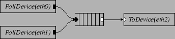
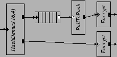
Figure 1 shows a simple Click configuration. In our configuration diagrams, black ports are push and white ports are pull; agnostic ports, which can connect to either push or pull ports, are shown as push or pull ports with a double outline. This configuration reads packets from network interfaces named eth0 and eth1, appends them to a queue, and transmits them out interface eth2. The s initiate pushes along the paths to the queue as packets arrive. The initiates pulls from the queue as the device hardware completes previous packet transmissions.
2.1 An IP Router
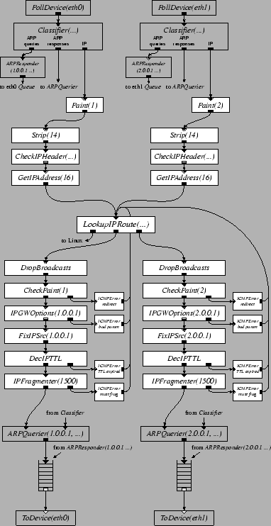
Figure 2 shows a basic 2-interface IP router configuration. Detailed knowledge of this configuration is not required to understand this paper; it's included to give a feel for the level at which one configures a Click router. The high-level flow of packets through Figure 2 is as follows. Each element reads packets from an input device. The separates ARP queries and responses from incoming IP packets. annotates each packet with the index of the interface it arrived on, for later use in generating redirects. removes the 14-byte Ethernet header, leaving just an IP packet. verifies that the IP checksum and length fields are valid. extracts the packet's destination address from the IP header. separates the packets according to which output interface they should be sent to; it also separates packets addressed to the router itself. The elements before the perform per-interface input processing; the elements after the perform per-interface output processing. The first stage in output processing is to drop any packet sent to a broadcast Ethernet address, since forwarding it would not be legal. detects a packet forwarded out the same interface on which it arrived, and arranges to generate an ICMP Redirect. processes hop-by-hop IP header options. rewrites the source address of any packet generated by the router itself to be the address of the outgoing interface. checks and decrements the TTL field, and fragments large packets. finds the Ethernet address associated with the next hop and prepends an Ethernet header; this may involve setting aside the packet while sending out an ARP query. Finally, the push path ends by depositing the packet in a . pulls packets out of the queue whenever the output device is ready to send.
2.2 Configuration-level ParallelismControl (i.e. a CPU thread) can enter a Click configuration at one of only a few schedulable elements: at a element, to check device hardware for new input packets and start push processing; at a , to initiate a pull for the next available output packet and send it to device output hardware; and at a element which initiates a pull through its input and pushes any resulting packet to its output. Once a CPU thread starts pull or push processing for a packet at a schedulable element, that thread must carry the packet through the configuration until it reaches a , a , or some other element that discards or otherwise disposes of the packet. For convenience, let a push path be a sequence elements that starts with a schedulable push element, such as , and ends with a , and let a pull path be a sequence of elements that starts with a and ends with a schedulable pull element, such as . These constraints on control flow mean that a Click configuration conveys a good deal of information about potential parallelism. CPUs executing completely disjoint paths will not interfere with each other at all. CPUs carrying packets along the same path may interfere with each other, though parallelism may still be available if the path contains multiple expensive elements. A common situation arises when paths from a number of elements converge on a , which in turn feeds a . The push paths from the s are mostly disjoint, conflicting only at the last element , so each can be profitably executed by a separate CPU. In contrast, the pull path from the to the is usually short and would cause contention if executed on multiple CPUs; in fact, SMP Click never executes any schedulable element on more than one CPU concurrently.
3 Design GoalsThe most obvious design goal of SMP Click is to run Click configurations on multiprocessor PC hardware. In order for it to be useful, however, it must achieve a number of related goals:
The second goal is reasonable because most Click configurations inherently allow for some parallelism. Any configuration with multiple network interfaces can read from and write to the different interfaces in parallel. Checking incoming packets for correctness and even lookup of destinations in routing tables can also often proceed in parallel for packets from different interfaces. For example, almost all of Figure 2 can proceed in parallel for packets arriving from different interfaces; contention first occurs either in the mutable ARP table in or in the queues. In support of the last goal, SMP Click allows users to perform a variety of configuration transformations that might increase parallelism, including the following:
See Section 6 for examples of some of these transformations and their effects on performance.
4 ImplementationUniprocessor Click, the predecessor to the work described here, runs in a single thread inside the Linux kernel. It schedules work by maintaining a work list of elements that want CPU time. These elements are typically of types , , and . Since these elements poll for the availability (or departure) of packets, and Click uses no interrupts, they must be called periodically. All pushes and pulls are initiated by elements on the worklist. SMP Click retains much of the structure of uniprocessor Click, but involves changes in a number of areas. These include scheduling the worklist on multiple CPUs, synchronization to protect mutable data in re-entrant elements, and special handling of devices, buffer free lists, and queues to enhance parallelism.
4.1 CPU SchedulingWhen it first starts, SMP Click creates a separate thread for each processor. Each thread runs schedulable elements from a private worklist in round-robin order, occasionally yielding control to Linux so user processes can make progress. This approach differs from most software routers built on top of traditional operating systems in that packet processing is not driven by packet arrival interrupts, hence device handling cannot starve packet forwarding [17]. Each thread has a private worklist in order to avoid the expensive synchronization operations associated with centralized worklists [1] and to allow processor affinity scheduling. Load balancing among these private worklists, however, is difficult to achieve for three reasons. One, Click never interrupts an element while it is processing a packet, so time-slicing is not possible. Two, since elements take different time to execute, merely balancing the number of elements on each worklist is not adequate. Three, because Click is not event driven, an idle element cannot remove itself from a worklist and rejoin the list later on when it is ready to process a packet. Consequently, most schedulable elements remain on the worklist even if they rarely have work to do. This means SMP Click cannot use work-stealing algorithms [1,] that steal work from other worklists when the local worklist empties. SMP Click offers two solutions for load balancing. It provides an adaptive load balancing algorithm that schedules elements onto different CPUs, providing good load balance. It also allows ambitious users to statically schedule elements based on SMP Click's performance measurement tools. We describe both approaches below.
4.1.1 Adaptive CPU SchedulingWhen an SMP Click router starts, one worklist contains all schedulable elements. Click maintains, for each schedulable element e, the average cost of that element, Ce. If adaptive CPU scheduling is used, a global scheduler rebalances the assignment of elements to worklists periodically. The scheduler sorts the schedulable elements in decreasing order based on Ce. It then iterates through the sorted list, assigning each element to the worklist with the least amount of total work so far. The cost of an element is the average number of cycles consumed by the push or pull processing initiated by this element each time it is called. To obtain this number, SMP Click periodically samples the number of cycles consumed by the element when it is called. This sampling technique does not introduce any noticeable performance overhead. The CPU scheduling mechanism described here provides three benefits. It balances useful work among the CPUs to increase parallelism, it avoids contention over a single work list, and it encourages affinity between particular tasks and CPUs to reduce cache misses.
4.1.2 Static CPU SchedulingAdaptive load balancing may not result in the best routing performance due to its ignorance of cache miss costs. If two elements that process the same packets (e.g. a element and the element that it sends packets to) are scheduled onto different CPUs, the cost of processing each packet increases due to cache misses. Thus, even if a balanced load is achieved, the router may still perform worse than when these two elements are scheduled onto the same CPU. Automatically instrumenting the packet processing code to detect cache misses would involve reading hardware performance counters, a costly operation. On the other hand, with some knowledge about the costs of different paths, a user can easily specify a good scheduling assignment for most configurations. For example, a four-interface IP router has eight schedulable elements: four elements and four elements. Because the path initiated by the is more expensive than the path initiated by the , a good scheduling assignment on four CPUs would schedule one and one on each CPU. Furthermore, to reduce the cost of cache misses, and elements that operate on the same interface should not be scheduled together, since they never process the same packets. Static scheduling can be specified in the form of a list of assignments of schedulable elements to CPUs. In addition, Click can be configured to measure and report the execution time of packet processing paths.
4.2 SynchronizationAny element instance in SMP Click might be executed simultaneously on multiple CPUs, so every element must protect its mutable data structures. The details are private to the implementation of each element type, since elements don't use each other's data. A number of different approaches prove useful. Many elements have no mutable state, and thus require no special synchronization. A typical example is the element, which simply removes bytes from the head of a packet. Some elements have state composed of just a counter. If the counter is rarely incremented, as in the case of an error counter, it can be updated with hardware atomic increment instructions. A typical example is the element, which maintains a count of invalid packets. Some mutable element state can be replicated per processor, so that it is never shared. For example, the IP routing table lookup element keeps a private per-CPU cache of recently used routes, rather than a single shared cache. Some elements protect their state with spin-locks, implemented with the x86 xchgw atomic exchange instruction. If a CPU acquires a lock that was last held by the same CPU, the xchgw executes quickly out of that CPU's cache; otherwise the xchgw involves a slow off-chip bus transaction. Thus, for data which is only occasionally written, SMP Click uses read/write locking in which each CPU has its own read lock, and a writer has to acquire all the read locks. and use this technique to protect their tables. An element instance that appears on the work list is executed by at most one CPU at a time. Thus and elements need not take special pains to prevent more than one CPU from communicating with the same device hardware. Device handling, the buffer free list, and queues need special attention for high performance, detailed in subsequent sections.
4.3 Device HandlingClick device drivers use polling rather than interrupts in order to avoid interrupt overhead. An alternate approach might have been to use the ``interrupt coalescing'' scheme supported by the Intel Pro/1000 F gigabit Ethernet cards we used, which lowers interrupt overhead by imposing a minimum delay between successive interrupts. The correct minimum delay parameter turns out to depend on the time required to completely process all packets that arrive on all interfaces between interrupts, which proved too difficult to predict. Another reason to prefer polling is that it eliminates the expense of synchronization between threads and interrupt routines. To maximize parallelism, SMP Click device drivers completely separate transmit and receive data structures. For example, the transmit routines are responsible for freeing transmitted packets, and the receive routines are responsible for giving the device fresh empty buffers. Polling a device that has no packets waiting needs to be very fast. In practice this means that the device's DMA descriptors should reside in host memory (not in device memory), and that the driver should be able to discover new packets just by looking at the descriptors. If the device is idle, the CPU will have already cached these descriptors, and checking them will be fast. It is also important that the driver and the device should never explicitly synchronize or directly communicate. The host should not read or write on-device registers to exchange information about new packets or free buffers; instead all such communication should take place indirectly through DMA descriptor contents. The Intel 21140 [7] is a good example of such a design. Unfortunately, the Intel Pro/1000 devices used for this paper's experimental results require the driver to write device registers to announce the addition of buffers to DMA descriptors. The SMP Click drivers reduce this overhead by batching such additions.
4.4 Buffer ManagementPacket buffers in a router usually go through a repeating life-cycle: they are allocated by a device driver, filled with incoming data by a device, processed by the router, transmitted, and then freed. SMP Click takes advantage of this regularity in a number of ways. SMP Click uses Linux's sk_buffs, which consist of a descriptive structure (containing lengths etc.) and a separate data buffer. sk_buff data is contiguous, which makes it easy to manipulate; lists of sub-buffers (as in BSD mbufs [16]) are mainly useful for host protocols in which headers and payload may be stored separately. The sk_buff allocator in Linux 2.2.18 is expensive. Allocating (or freeing) an sk_buff requires two locking operations, since the structure and the data buffer are allocated separately. Since Linux has only one free list, it is likely that an sk_buff freed on one CPU will be allocated on another, causing needless cache misses. SMP Click avoids these costs by handling sk_buff allocation itself. It maintains a separate free list for each CPU, implemented as a circular array. Each CPU frees only onto its own free list, so freeing never requires locking. When a CPU needs to allocate a packet, it tries to do so from its own free list to benefit from the possibility that the buffer is already cached. If its free list is empty, it allocates a packet from another CPU's free list. The other list is chosen in a way that makes it likely that each CPU has at most one other CPU allocating from its list. Since it is common for some CPUs to be dedicated to receiving only, and some to transmitting only, this matches up producers and consumers of free packets. Producers never need to lock, and consumers usually acquire a lock that they were the last to hold, which is fast. As an additional optimization, both allocation and freeing are batched, decreasing free list manipulation costs. Batching is possible since only device drivers ever free or allocate, and they can arrange to defer such actions until they can perform them on many device DMA descriptors at once.
4.5 Queueselements are the primary points at which packets move from one CPU to another, so accesses to data structures and enqueued packets are likely to cause cache misses. In addition, multiple threads may enqueue and dequeue from a , so it must protect its data structures. In many common cases, however, these costs can be eliminated. Most s are used to feed output devices. Two s can share a single , if they are feeding parallel links to another router, but this is not a common situation. SMP Click automatically eliminates locking for dequeues in the usual case in which only one pulls from a . This is possible because a is implemented with a circular array of buffer pointers, and the enqueue and dequeue operations modify different pointers into that array. Most s are fed by multiple s, and must be prepared for concurrent enqueues. SMP Click enqueues with an atomic compare and swap instruction to avoid some locking overhead.
4.6 Batching and PrefetchingSMP Click processes packets in batches to reduce cache coherency misses, to amortize the cost of locks over multiple packets, and to allow effective use of memory prefetch instructions. Batching is implemented by , , and elements; other elements and all inter-element communication are one packet at a time. dequeues up to eight packets from the device DMA queue at a time, then sends them one by one down the push path. Batching the device dequeues allows the driver to usefully prefetch DMA descriptors and packet contents, which are not in the CPU cache since they were last written by device DMA. Batching also allows the driver to allocate new receive buffers in batches, amortizing the overhead of locking the free list. tries to pull multiple packets from its upstream each time it is called by the scheduler. It enqueues these packets onto the transmit DMA ring. After the entire batch has been enqueued, notifies the device of the new packets. Batching allows the device driver to amortize the cost of this notification over many packets. In addition, frees transmitted packets in groups. Multiple packets must be enqueued in a in order for batching to be effective. To ensure that the can pull several packets at a time from the , the dequeue code pretends that the queue is empty until either eight packets have been enqueued, or a short time has elapsed. This also allows the enqueuing CPU to keep the queue data structures in its cache while it enqueues a few packets; otherwise the enqueuing and dequeuing CPUs would fight over those cache entries.
5 Performance of Naive RoutersThis section examines SMP Click's performance with some configurations originally designed for use on uniprocessor Click; the results reflect on SMP Click's goal of increased performance for untuned configurations.
5.1 Experimental SetupThe experimental setup consists of five Intel PCs running Linux 2.2.18. One of the PCs acts as a router, with a separate full-duplex point-to-point gigabit Ethernet link to each of the other four ``host'' PCs. The host PCs send packets into the router to be forwarded to the other host PCs. The router's IP routing table contains just the entries required for the four hosts. The router is a Dell PowerEdge 6300, with four 500 MHz Intel Pentium III Xeon CPUs, an Intel 450NX chipset motherboard, and 1GB of RAM. The hosts have dual 800 MHz Pentium III CPUs, ServerWorks LE chipsets, and 256MB of RAM. All the network devices are Intel Pro/1000 F gigabit Ethernet cards, connected to the motherboards with 64 bit 66 MHz PCI. All experiments use 64-byte IP packets. Each packet includes Ethernet, IP, UDP or TCP headers, a small payload, and the 4-byte Ethernet CRC. When the 64-bit preamble and 96-bit inter-frame gap are added, a gigabit Ethernet link can potentially carry up to 1,488,000 such packets per second. Each host can send up to 876,000 packets per second, using software that closely controls the send rate. The hosts can also receive reliably at the same rate.
5.2 IP Performance
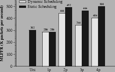
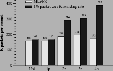
Figure 4 shows SMP Click's performance when forwarding IP packets with a four-interface version of the configuration in Figure 2. In these experiments, each host sends IP packets to the other three hosts for 60 seconds. The y-axis represents the maximum loss-free forwarding rate (MLFFR). The x-axis represents five experimental scenarios: uniprocessor Click on uniprocessor Linux, and SMP Click on SMP Linux with one to four CPUs. We ran two experiments with each scenario, one with adaptive load balancing, one with static scheduling. In the static scheduling experiments, each was scheduled on the same CPU as one of the three s that it forwards packets to. With two CPUs, two s and two s are scheduled on each CPU. With three CPUs, two s and a are scheduled on two of the CPUs, with the remaining two s on the third. With four CPUs, each CPU runs one and one .
Table 1 helps explain these results by showing the CPU-time costs of forwarding a packet, measured with Intel Pentium cycle counters. The actual forwarding rates are close to those implied by the CPU time measurements. For example, Table 1 shows that it takes 4.18 microseconds of CPU time to forward a packet on a 2-CPU router, implying that each CPU should be able to forward 239,234 packets per second, and that the two CPUs together should be able to forward 478,468 packets per second; this is close to the actual rate of 444,000 to 492,000 packets per second measured in Figure 4. As the number of CPUs increases, the per-packet CPU time also increases. This is because synchronization and cache misses impose costs that increase with the number of CPUs. The largest increase occurs for push processing, which includes enqueuing on s; the reason is that more CPUs cause more contention between enqueuing and dequeuing. The other expensive increases occur when allocating and freeing buffers, especially for the three CPU case. With three CPUs, one of the CPUs does not have any elements. Thus it must allocate buffers from another CPU's free list, resulting in cache misses on the buffer data structure and on the synchronized free list. Finally, Pull, Xmit, and Clean operations operate on dequeued buffers. As the number of CPU increases, they are more likely to have been touched last by another CPU.
Table 2 illustrates contention between CPUs by showing the number of system bus operations per packet. A bus operation is caused by an L2 cache miss, a write of shared/cached data, or an acquisition of a lock by a CPU other than the CPU that held it last. The cost of sharing s between enqueuing and dequeuing CPUs is evident in the increased number of bus operations on the Push and Pull lines as the number of CPUs increases. The reason that dynamic load balancing does not work as well as static scheduling in Figure 4 is that the dynamic scheduler sometimes puts the and of the same interface on the same CPU. This misses opportunities to do both push and pull processing for some packets on the same CPU. Some of the push and pull costs in Table 1 are due to IP processing. By using a much simpler configuration, essentially consisting of just device drivers, the potential performance of the underlying machine can be estimated. With a configuration that directly passes packets from each input interface through a to a statically paired output with no intervening processing, SMP Click can forward 528,000 packets per second on one CPU and 566,000 packets per second on two or four CPUs. Each packet is processed entirely by a single CPU. The above tests emphasize per-packet overheads, since they use small packets. With 200 byte UDP packets, the IP router has a MLFFR of 240,000 packets per second on four CPUs, or 366 megabits per second. With 1024 byte UDP packets, the MLFFR is 90,000 packets per second on four CPUs, or 703 megabits per second. This section shows that, with the Click SMP architecture, the benefits of parallelizing IP processing outweigh the costs of synchronization and data movement between CPUs by a relatively small margin. The next section demonstrates that parallelization is much more attractive for more compute-intensive packet processing.
5.3 Virtual Private Network Gateway
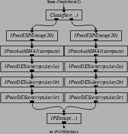
Figures 5 and 6 present Click configuration fragments that implement part of IPSec [12]. Inserting these elements into the IP router in Figure 2 produces a Virtual Private Network (VPN) gateway. The intent is that Figure 5 be inserted into the output processing of the router's link to the outside world, to authenticate, encrypt, and encapsulate packets sent along a VPN tunnel to a similar remote router. Figure 6 performs the inverse operations for packets arriving from the interface to the outside world. The configurations shown use SHA-1 for authentication and 3DES for encryption.
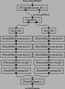
For space reasons, Figure 5 and 6 show configurations with only two VPN tunnels, while our performance evaluation uses eight. These tunnels are established statically, using elements as the input and output security association databases. The traffic used to test the VPN configuration is generated as follows. Two hosts are ``internal'' hosts; the other two are external hosts. Each internal host generates eight streams of ordinary 64-byte IP packets, four to one external host, and four to another. The VPN router authenticates, encrypts, encapsulates, and forwards these packets. Each external host generates eight streams of encapsulated, authenticated, and encrypted packets, four to each internal host. The VPN router unencapsulates, decrypts, authenticates, and forwards these packets as well.
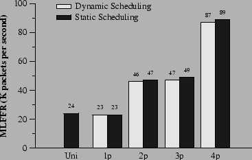
Figure 7 shows the forwarding performance of the VPN router in 60 second experiments. The static CPU scheduling experiments used the same scheduling assignment as the IP router. The VPN scales better than the IP router because computation performed on each packet is more expensive and dominates the overhead of cache misses and synchronization. For the same reason, adaptive load balancing works as well as static scheduling. The reason the performance is no higher with three CPUs than with two is that one of the three CPUs has to handle encryption and decryption for two input interfaces. That CPU runs out of cycles, and starts dropping packets, when the other two CPUs are still only half utilized. This limits the loss free forwarding rate of the whole router. As a crude comparison, a $10,000 commercial VPN box with hardware assisted 3DES encryption was recently rated at 27 Mbps for 64 byte packets (i.e. 55 Kpps) [21].
5.4 NAT Performance
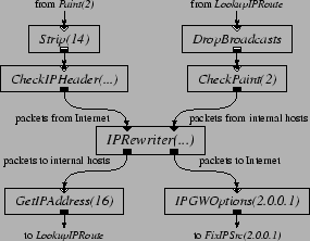
Figure 8 shows a configuration fragment that, when inserted into the IP router configuration, implements a network address translator [9]. The router sends packets from ``inside'' hosts to external destinations to the upper-right input port of the [15]. The changes these packets' source IP addresses to an externally visible address, rewrites the source TCP port numbers, and emits them out the lower-right output port; from there they are transmitted to the external Internet. The dynamically maintains tables that allow it to map all the packets of each connection in a consistent way, and allow it to associate incoming packets from the outside world with the relevant connection. Before the routing table lookup, each incoming packet enters the via the upper-left input port. The changes the destination IP address and TCP port number to that of the original connection, and sends the packet out on the lower-left output port. The correct destination route is then determined, using the updated destination IP address, by . An handles mappings for a single externally visible IP address. It gives each connection its own externally visible port number. The remembers which connections have sent TCP FIN (connection close) messages, and deletes any such connection from its tables after 30 seconds. does this deletion incrementally: each time it sees a TCP SYN (connection setup) message, it checks to see if the oldest closed connection is 30 seconds old. This deletion policy means that each port an allocates cannot be used again for at least 30 seconds. An uses ports 1024 through 65,535, and thus can handle no more than 2,150 connections per second. To avoid this limit, the experiments described here use a configuration with 32 elements, each with its own IP address. A spreads the flows from the internal hosts over the based on destination address. When a packet arrives from the outside world, an decides which to send it to, based on destination address.
The traffic used to test the NAT configuration in Figure 8 is generated as follows. Two hosts are considered internal hosts, and two are external hosts. Each internal host maintains 100 concurrent connections to each of the external hosts. For each connection, an internal host repeats the following: it chooses random port numbers, sends a SYN packet, 8 64-byte data packets, and a FIN packet, then starts over. The external host echoes each packet, exchanging fields as appropriate. Figure 9 shows the NAT's packet forwarding performance as the number of CPUs increases. Static scheduling is used, and the assignments are the same as those in Section 5.2. The experiments run for 90 seconds, of which only the last 60 are included in the statistics; this allows time for the tables to fill up and for entries to start being deleted. Figure 9 shows that the MLFFR of the NAT does not increase significantly with more processors, even though the NAT requires more CPU time than IP forwarding alone. The packet loss rate experienced by the NAT, however, remains tiny for input rates substantially greater than the MLFFR. For example, with 4 CPUs, the loss rate does not exceed 0.1% until the offered load is above 270,000 packets per second. We suspect the persistent tiny loss rate is caused by lock contention. Contention for locks may occur when a attempts to push a packet through a rewriter while another is pushing a packet through the same rewriter, but on a different CPU. With 32 rewriters, the possibility of contention is small. However, each contention is potentially costly: the cycles spent spin-waiting for the lock may delay scheduling of a and cause a device's receive DMA queue to overflow.
5.5 Enforcing Quality of ServiceFigure 10 shows a configuration that provides a simple quality of service guarantee. Inserted before the element in the IP router in Figure 2, this configuration fragment classifies packets into three priorities based on the IP header's Differentiated Services Code Point field (DSCP) [22]. Each priority level is queued separately, and the element always sends packets from higher priority queues in preference to lower. The configuration applies SHA-1 authentication and 3DES encryption to the medium priority traffic, much as described in Section 5.3. A element initiates this processing, so it can be done on a CPU separately from input and output processing. The element only pulls packets from upstream queues if the downstream queue is not full; this helps the configuration enforce priority when the output device is slow.
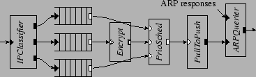
Figure 11 shows the uniprocessor performance of this configuration. The traffic used to test this router consists of three streams of UDP traffic from one host to another. The sender sends a high-priority and a low-priority stream at a constant 70,000 and 50,000 packets per second, respectively. It sends the third stream, of medium-priority traffic, with varying rate. Figure 11 shows that as the input rate of medium priority traffic increases, the forwarding rate for high priority traffic does not change. There is enough spare CPU time that the medium priority traffic can be forwarded at up to 10,000 packets per second without disturbing the low priority traffic. Above that rate the router devotes CPU time to encrypt medium priority traffic at the expense of low-priority processing, so the low priority forwarding rate decreases. The specific mechanism is that the packet scheduling done by the implicitly schedules the CPU, since the decides which pull path the CPU executes. When the medium priority input rate reaches 14,000 packets per second, the forwarding rate levels off because all available CPU time has been taken from the low priority traffic.
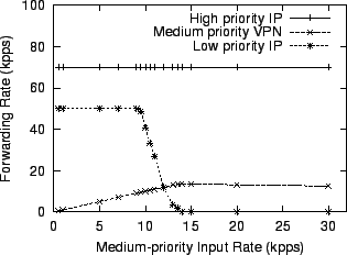
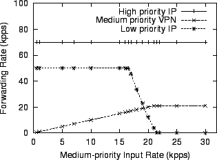
Figure 12 shows that on four CPUs, the same IP router can sustain the low priority traffic even when the input rate of medium priority traffic approaches 17,000 packets per second. Furthermore, the maximum forwarding rate for medium priority traffic reaches 21,000 packets per second. The router uses dynamic scheduling. This causes three CPUs to handle device interactions and IP header processing; the remaining CPU runs the element shown in Figure 10, and thus performs the VPN encryption as well as moving packets of all priorities through the configuration fragment. These experiments show that SMP Click configurations that express packet priority also naturally imply CPU priority. In addition, priority constraints do not prevent SMP Click from obtaining a degree of increased performance from multiple CPUs.
6 Exposing ParallelismEven if a router's task has a good deal of potential parallelism, any given configuration may fail to expose that parallelism. Consider the VPN router in Section 5.3, but with only two interfaces instead of four. Such a configuration has four schedulable tasks. Most of the processing occurs in the push paths initiated by the two tasks, so the CPUs running the tasks may spend much of their time idle. A better balance of load across the CPUs would increase performance, but the configuration doesn't allow for it. This section presents and evaluates configuration tuning techniques that yield improvements in performance by exposing more parallelism. One technique splits packets into multiple flows which can be processed in parallel. A second technique breaks expensive processing into pipeline stages that can be executed in parallel. Finally, we show that configuration rewriting need not affect quality of service guarantees.
6.1 Parallel Flow Processing
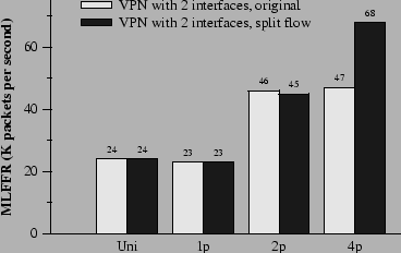
Figure 13 shows the performance of the VPN configuration with only two Ethernet interfaces. Two hosts participate in these experiments. One host sends unencrypted packets to the router. The router encrypts the packets and forwards them onto the other host. The second host sends encrypted packets to the router. The router decrypts these packets and forwards them to the first host. Since encryption and decryption only occur on packets going to and arriving from one of the two devices, one performs all the encryption work, and one performs all the decryption work. This suggests that, on a four-CPU machine, the two CPUs running s are mostly idle. Consequently, the configuration doubles its performance on two processors, but its performance on four processors does not improve. More parallelism could be created by moving expensive elements to the pull paths, allowing elements to share the expensive work. This turns out to be awkward; for example, at that point the packets already have Ethernet headers. We create more parallelism by splitting packets into multiple flows. Two sets of , , and elements are inserted before both the encryption and decryption elements in the VPN configuration, as suggested in Figure 3. This optimization creates two new schedulable elements: a element that handles half of the packets that need to be encrypted; and a element that handles half of the packets that need to be decrypted. The black bars in Figure 13 show that this optimization produces a 45% performance improvement on four CPUs over the untuned configuration. The improvement is not higher because of the cost of moving each packet from one CPU to another through the . This rewriting technique is not universal. For example, it decreases the performance of a router that does just IP forwarding between two interfaces. This is because the cost of vanilla IP forwarding is already low enough that parallelization cannot overcome the cost of the extra elements and cache misses.
6.2 Pipelined Packet ProcessingConsider a node in an overlay network consisting of a mesh of encrypted VPN tunnels. Such a node may have to decrypt a packet arriving on one tunnel, only to encrypt it again (with a different key) when forwarding it out a second tunnel. Each would be responsible for both decryption and encryption. On the other hand, the s would have relatively little work. More parallelism could be created by splitting packets into multiple flows, as described in Section 5.3. Parallelism can also be created by pipelining encryption and decryption, as shown in Figure 14. The technique is to insert a and a between the decryption and encryption processing. With this optimization, each performs decryption in parallel with encryption performed by the .

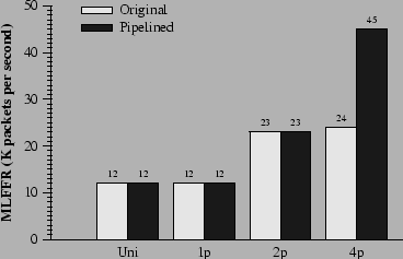
Figure 15 shows the effectiveness of this technique. It almost doubles the performance of the 4-CPU machine, and causes performance to scale almost linearly from one to four CPUs.
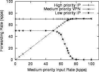
6.3 Maintaining Quality of ServiceThe performance improvement with additional CPUs of the QoS configuration described in Section 5.5 is limited, since a single CPU executes the and thus the encryption. One solution might be to add a new dedicated to the encryption of medium-priority traffic, leaving the old to process only high and low priority traffic. Since a separate CPU could run the new , performance should improve. Rewriting the configuration this way, however, would violate the intended packet priority semantics. The old would send low-priority packets even if there were a backlog of medium-priority packets, since only the new would be able to process medium-priority packets. The intent of priority, however, is that low-priority packets should only be sent if there are no high or medium priority packets waiting.
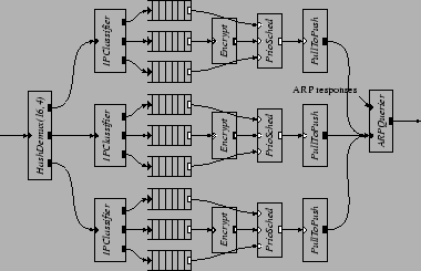
A better approach is to replicate the whole QoS configuration and run the replicas in parallel. We replicate the configuration three times, as shown in Figure 16. The element breaks packets into three streams; each stream has its own priority scheduler. The three elements run on three CPUs, while the remaining CPU performs all the device handling and IP header processing. While it is possible that low priority packets are pushed through on one processor while there are a backlog of medium or high priority packets on another, such scenario is unlikely when there are many flows with different destination IP addresses. Figure 17 shows the effectiveness of this technique. The new router can sustain the low priority traffic even when the input rate of the medium priority VPN traffic exceeds 50,000 packets per second. The maximum forwarding rate for the medium priority traffic reaches 70,000 packets per second, a factor of five improvement over the uniprocessor performance shown in Figure 11.
7 Related WorkCommercial routers such as the Cisco 7500 [26] often contain multiple CPUs to increase performance. The hardware of such routers usually dedicates each CPU to a particular task. This structure provides high performance for its intended task, but allows little flexibility. For example, one line card's CPU cannot help in the processing of packets from a different line card. Commercial SMP routers do exist. The Nortel Contivity 4500 VPN switch [23] uses dual SMP PC processors to encrypt and decrypt packets for multiple VPN tunnels in parallel. Its hardware is similar to SMP Click's, though its software structure is not publically known. In a different approach to multiprocessor routing, network processors [10,] have appeared recently that integrate multiple RISC CPUs onto a single chip. These chips could be placed on router line cards, replacing ASICS; their advantage is that it is easier and faster to write software than to design ASIC hardware. A variant of SMP Click could be used to structure that software in a way that takes advantage of the multiple CPUs. However, current generation network processors have a limited program memory in their processing elements, which limit their use to small pieces of tight code [25]. Previous work in the area of parallelizing host network protocols [20,19,3,24] has compared layer, packet, and connection parallelism. One of their conclusions is that performance is best if the packets of each connection are processed on only one CPU, to avoid contention over per connection data. To a first approximation this is a claim that a host's protocol processing tasks can be decomposed into symmetric and independent per-connection tasks. This situation does not generally hold in a router. If the router has no per-connection state, then there is no symmetry and independence to exploit. Worse, device handling is often a large fraction of the total work, but cannot easily be divided up among many CPUs. For these reasons, SMP Click needs to be able to exploit a wider range of kinds of parallelism than host implementations. Blackwell [4] and Nahum et al. [18] investigate the interaction of host protocol processing and caching on uniprocessors. They observe that instruction cache misses are often a dominant factor in performance, and observe that batch processing of multiple packets at each protocol layer can help. In contrast, we observe very few instruction cache misses in SMP Click, probably because IP forwarding is simpler than host TCP processing. SMP Click nevertheless benefits from batching, though the reason is that batching helps avoid contention at the points where data must move between CPUs or between CPU and device. SMP Click's device handling uses ideas explored in the Osiris [8] network adaptor project to maximize concurrency between CPU and device, in particular lock-free DMA queues and avoidance of programmed I/O.
8 ConclusionThis paper makes the following points about parallelization on multi-processor routers, in the context of SMP Click:
AvailabilitySMP Click is publically available. It can be downloaded from the Click project web page, at http://www.pdos.lcs.mit.edu/click/.
AcknowledgmentsEddie Kohler and Massimiliano Poletto helped us enormously with Click and . We also would like to thank Alex Snoeren for his work on the IPsec elements. We used Eric Young's DES and SHA-1 implementations. Michael Ernst, Frans Kaashoek, Rob Miller, and the anonymous reviewers provided us with invaluable feedback.
|
|
This paper was originally published in the
Proceedings of the 2001 USENIX Annual Technical Conference, June
25Đ30, 2001, Boston, Massachusetts, USA.
Last changed: 3 Jan. 2002 ml |
|