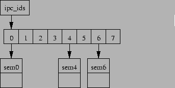
This section presents a graphical demonstration of how grow_ary(), ipc_rmid(), and ipc_lock operate. The figures in this section are abbreviated forms of Figure 8 and Figure 9. Figure 14 shows a system with three semaphores allocated out of a maximum of eight that could be accommodated.
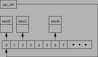
The results of a concurrent grow_ary(), ipc_rmid() and creation of a new semaphore are shown in Figure 15, but with the additional ipc_id array elements omitted from the figure. At this point, a concurrent ipc_lock() would see semaphore 4 as being deleted (note the "D" in the diagram), and would have no way of reaching the newly created semaphore 2. The lack of visibility to semaphore 2 is legal, since this semaphore was created after ipc_lock() started execution. A subsequent ipc_lock() would see semaphores 0, 2, and 6, but would not newly deleted semaphore 4.
Finally, Figure 16 shows the state of the system after a grace period. The old ipc_id array has been freed, as has semaphore 4. Because the grace period has completed, there can no longer be any references either to the old array or to the now-deleted semaphore 4.