We have implemented a storage server system using a PC cluster. The storage system manages multiple virtual volumes (virtual disks). A virtual volume can be implemented using a single or multiple physical disk partitions. Similarly to other clustered storage system [35], our storage system runs on a cluster of four PCs. Each PC is 400 MHz Pentium II with 512 KBytes second level cache and 1 GB of main memory. All PCs are connected together using Giganet [22]. Clients communicate with storage server nodes using the Virtual Interface (VI) communication model [29]. The peak communication bandwidth is about 100 MBytes/sec and the one-way latency for a short message is about 10 microseconds [22]. Data transfer from Oracle's buffer to the storage buffer uses direct DMA without memory copying. Each PC runs Windows NT 4.0 operating system. The interrupt time for incoming messages is 20 microseconds. Each PC box holds seven 17 GBytes IBM SCSI disks, one of which is used for storing the operating system. The bandwidth of data transfers between disk and host memory is about 15 Mbytes/sec and the access latency for random read/writes is about 9 milliseconds. Each PC in our storage system has a large buffer cache to speed up I/O accesses.
We have implemented
both MQ and LRU as the cache
replacement algorithms. The parameters of the MQ algorithm are
the same as described in the previous section. It uses
eight queues. The history buffer size is four times the number of cache
blocks. The ![]() parameter is set dynamically after the warmup
phase and adjusted periodically using the statistic information [44].
parameter is set dynamically after the warmup
phase and adjusted periodically using the statistic information [44].
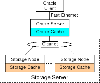
We measure the performance using the TPC-C benchmark [27] running on the Oracle 8i Enterprise Server [5]. Figure 6 gives the architecture of our experiments. The hardware and software setups are similar to those used for collecting the Oracle Miss Trace-128M. The Oracle 8i Server runs on a separate PC, serving as a client to the storage system. It accesses raw partitions directly. All raw I/O requests from the Oracle server are forwarded to the storage system through Giganet. The Oracle buffer cache is configured to be 128 MBytes. Other parameters of the Oracle Server are well tuned to achieve the best TPC-C performance. Each test runs the TPC-C script on an Oracle client machine for 2 hours. The Oracle client also runs on a separate PC which connects to the Oracle server through Fast Ethernet. The TPC-C script is provided by the Oracle Corporation. It simulates 48 clients, each of which generates transactions to the Oracle server. The TPC-C benchmark emulates the typical transaction processing of warehouse inventories. Our database contains 256 warehouses and occupies 100 GBytes disk space excluding logging disks. Logging disk data is not cached in the storage system. The storage system employs a write-through cache policy.