Arunesh Mishra-(1) , Eric Rozner-(2) , Suman Banerjee-(2) , William Arbaugh-(1)
(1)-University of Maryland, College Park. (2)-University of Wisconsin, Madison.
Interference has always been considered as an unavoidable peril in wireless networks. A single data transmission is useful to some nodes and becomes interference to others. Based on channel of origin, interference can be categorized into co-channel (from transmissions on the same channel as the receiver) and adjacent-channel (transmissions on adjacent and overlapping channels).
In this paper, we define specific mechanisms that can transform partially overlapped channels into an advantage, instead of a peril. We construct simple analytical and empirical models of such interference occurring in IEEE 802.11 networks, and illustrate two scenarios where such interference can be exploited. First, we apply partially overlapping channels to improve spatial channel re-use in Wireless LANs (WLANs). Second, we leverage such channels to enable nodes with a single radio interface to communicate more efficiently with their peers in 802.11 ad-hoc mode potentially using multi-hop paths. We evaluate both capabilities through testbed measurements.
|
The term adjacent channel interference can be contrasted to co-channel interference which occurs from transmissions on the same channel. In 802.11 and other wireless networks, adjacent channel interference is considered a peril. In order to avoid this peril, two simultaneously communicating nodes that are in close proximity are assigned to different non-overlapping channels, i.e., channels 1, 6, and 11 in 802.11b are non-overlapping. For example, in a inbuilding WLAN with multiple APs, interfering APs are assigned to different non-overlapping channels. Traditionally, in the literature on channel assignment algorithms, the notion of availability of a set of N channels has inherently implied that they are non-overlapping. This is why the number of available channels in 802.11b networks is considered to be three. However, many channel pairs in the ISM band overlap partially. Given that wireless spectrum is a scarce resource, in this paper we discuss the basic concepts behind building techniques to carefully exploit the partially-overlapped nature of channels for efficient spectrum management.
Consider a simple experiment where a transmitting station is placed on channel 6, and a receiving station is moved from channel 1 through 11.
The two stations are placed in close proximity to each other to preclude effects of signal attenuation
due to distance.
Table 1 shows the signal-to-noise ratio (SNR) of the received
signal on channels
![]() . The SNR is normalized to a scale of
. The SNR is normalized to a scale of ![]() with 1
denoting the maximum signal received and 0 the minimum (indicating background noise level).
We can see that the interference between channels 1 and 6, and channels
6 and 11 is minimum - hence they are considered non-overlapping. However, there
exist other channel pairs (eg:-
with 1
denoting the maximum signal received and 0 the minimum (indicating background noise level).
We can see that the interference between channels 1 and 6, and channels
6 and 11 is minimum - hence they are considered non-overlapping. However, there
exist other channel pairs (eg:-
![]() and
and
![]() ) where
the interference is fairly low.
) where
the interference is fairly low.
We define a term Interference-factor or simply I-factor denoted by ![]() as the extent of overlap between channels
as the extent of overlap between channels ![]() and
and ![]() . If
. If ![]() denotes
the power received at a given location of a particular signal, and
denotes
the power received at a given location of a particular signal, and ![]() denote the power received
of the same signal at the same location on channel
denote the power received
of the same signal at the same location on channel ![]() , then
, then ![]() is defined
as
is defined
as
![]() .
. ![]() gives the fraction of a signal's power on channel
gives the fraction of a signal's power on channel ![]() that
will be received on channel
that
will be received on channel ![]() . Table 1 thus shows
. Table 1 thus shows ![]() normalized to
a scale of
normalized to
a scale of ![]() .
I-factor can be calculated analytically
as well as empirically and does not depend
on the radio propagation properties of the environment (i.e. open space or indoors). It
depends on the extent of frequency overlap between the signals on channels
.
I-factor can be calculated analytically
as well as empirically and does not depend
on the radio propagation properties of the environment (i.e. open space or indoors). It
depends on the extent of frequency overlap between the signals on channels ![]() and
and ![]() .
.
We believe that ours is the first systematic effort on taking advantage of partial overlap among channels in two different settings -- WLANs and mesh networks. Each scenario illustrates a novel conceptual notion of exploiting the overlap among channels. To achieve some desired benefits we will leverage the following two observations. 1) As shown in Table 1 partial overlap among two channels reduces the signal strength of a transmission on one channel as received on the other (when compared to using the same channel). This improves the spatial re-use of channels which refers to how frequently a single channel can be re-used without interference. 2) Partially overlapped channels will allow communication between two nodes operating on non-overlapped channels, by forwarding traffic among them. We describe the two settings next.
 |
WLAN scenario: In a WLAN, an AP and its associated clients which form a basic service set (BSS), communicate on a single channel. Two APs can operate on the same channel as long as they do not interfere with each other. Better spatial re-use of channels brings about improvement in the network's throughput capacity as a whole [9]. Specifically in a WLAN, this allows the placement of more APs without interference and thus providing better service to an increased number of clients.
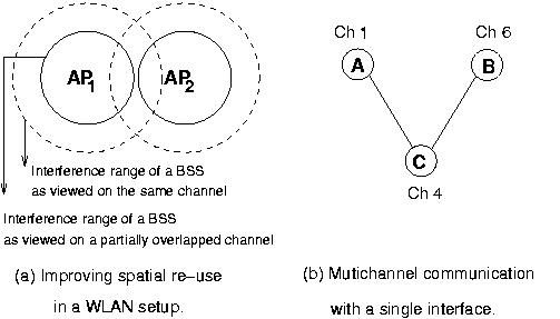
Neighboring APs in a WLAN are typically spaced sufficiently far apart so as to maximize the region of coverage while allowing some overlap for handoffs to occur smoothly. Figure 1(a) shows two APs and the interference range of their BSS which is the distance upto which transmission from the AP or an associated client would interfere (circular ranges for illustration only). Here these APs will have to be assigned to non-overlapping channels, or the APs will have to be spaced further apart to allow them to operate on the same channel. Instead of assigning them to non-overlapping channels, one can assign them partially overlapping channels such that the signal attenuation due to the partial overlap makes the interference negligible (i.e. the signal strength degrades to a tolerable level). Conceptually, this can be thought of as reduction in the interference range of an AP's BSS as viewed by a receiver on an adjacent overlapping channel. The reduction in the interference range increases with increased separation among the channels, with complete reduction perceived over non-overlapping channels.
It may appear that similar reduction in BSS size can be achieved by reducing transmission power of the APs. Unfortunately such a change does not lead to the same level of spectral use for two reasons. 1) Although by reducing transmission powers in 802.11b networks APs can be brought as close to each other as in the adjacent channel case, the number of channels that can be utilized is still three (and not four). 2) Reduction in transmission power reduces the signal to noise ratio in the AP-client interaction and adversely affects performance for clients. Hence, by exploiting adjacent channel interference we can get much better performance than by just reducing transmission power at APs. We evaluate this effect over TCP/UDP throughputs and MAC level collisions as measured in testbed environments in Section 3.
Mesh networks scenario: Consider a very simple mesh network setting with three nodes each having just one radio interface (Figure 1(b)). In general, if node A wants to communicate with node B, both these nodes need to use the same channel. However, let us assume that due to assignment of channels to other neighboring nodes, A and B need to be assigned to channels 1 and 6 respectively. However, if node C can be assigned to channel 4, then there are partial overlap between channels assigned to A and C as well as between B and C. Hence C can route traffic from A to B, using the partially overlapping properties of channels. Such opportunistic mechanisms can have non-trivial impact on the routing system used by the mesh network. In general, mesh network nodes where the number of interfaces available is less than the number of non-overlapping channels provided by the physical layer (such as 12 in 802.11a) can utilize such optimizations to communicate with nodes on multiple channels providing increased flexibility to the routing infrastructure used by the network. We evaluate this using experiments in Section 4. Next section presents the analytical basis behind spatial re-use.
We develop analytical reasoning behind using partially overlapping channels to improve spatial re-use of spectrum. We borrow some of the terminology used in [10] for the discussion below.
For the simplicity of discussion, we will assume an open-space
environment, in which
the path loss of a signal is usually modeled by a two-ray
ground propagation model [7]. Let ![]() is the distance between the receiver
and the transmitter.
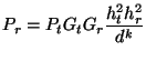
According to this model, in the open space environment, the received power
is the distance between the receiver
and the transmitter.
According to this model, in the open space environment, the received power ![]() of a
signal from a sender at distance
of a
signal from a sender at distance ![]() is given by
is given by
In Equation 1, ![]() and
and ![]() are the antenna gains of the
transmitter and the receiver respectively.
are the antenna gains of the
transmitter and the receiver respectively. ![]() and
and ![]() are the height of
both antennas.
are the height of
both antennas. ![]() is the transmission power at the sender.
The path loss, parameter
is the transmission power at the sender.
The path loss, parameter ![]() , typically is a value between 2 and 4.
, typically is a value between 2 and 4.
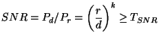
A signal arriving at a receiver can be demodulated correctly if the signal-to-noise ratio(SNR) is above a certain threshold (say ![]() ).
Say, a transmitter T and receiver R are separated
by distance
).
Say, a transmitter T and receiver R are separated
by distance ![]() , while another sender S (potentially causing interference) is
at a distance
, while another sender S (potentially causing interference) is
at a distance ![]() from the receiver R and on the same channel. Let
from the receiver R and on the same channel. Let ![]() denote the receiving power of
the signal from the transmitter T, and
denote the receiving power of
the signal from the transmitter T, and ![]() the power of the signal from S at
R. Thus, the SNR is given as
the power of the signal from S at
R. Thus, the SNR is given as
![]() , where
, where ![]() is the
ambient or thermal noise in the environment around the receiver R. For simplicity of
analysis, we neglect
is the
ambient or thermal noise in the environment around the receiver R. For simplicity of
analysis, we neglect ![]() compared to
compared to ![]() , and assume homogeneous radios. We have,
, and assume homogeneous radios. We have,
 |
(2) |
| (3) |
Thus, to successfully receive a signal, the interfering nodes must be at least
![]() distance away from the receiver.
distance away from the receiver.
Now, if T and R were on channel ![]() and the sender was on channel
and the sender was on channel ![]() , the minimum separation
between S and R would become
, the minimum separation
between S and R would become
![]() , where
, where ![]() denotes the
I-factor (see Table 1) as defined in Section 1. Note that since
denotes the
I-factor (see Table 1) as defined in Section 1. Note that since
![]() , this
new distance is less than
, this
new distance is less than
![]() , thus allowing the stations to get closer without incurring interference.
This improves the spatial re-use of the wireless spectrum.
We show how this concept can improve channel assignment in WLANs next.
, thus allowing the stations to get closer without incurring interference.
This improves the spatial re-use of the wireless spectrum.
We show how this concept can improve channel assignment in WLANs next.
 |
Channel assignment to APs in a wireless LAN is typically performed statically by the network adiminstrators after performing an RF site survey, or autonomously by the APs performing a ``least congested channel search (LCCS)'', i.e., identifying a channel which has low interference. Both approaches have been shown to have a number of inefficiencies, and other dynamic and distributed approaches have been proposed [4,5]. Here we show using a simple example how partially overlapping channels can yield improved network throughput and can be complimentary to existing channel assignment methods.
 |
 |
 |
| (A) UDP throughput | (B) TCP Throughput | (C) TCP throughput at 11 Mbps in a second office-building
environment.
|
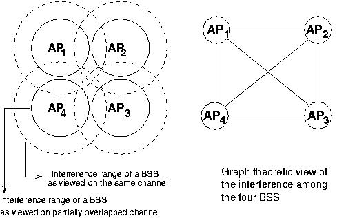
Consider the WLAN setup shown in Figure 2. The dashed circle shows the size of an AP's cell or the basic service set (BSS). This region is the distance upto which a transmission from either the AP or a client associated to the AP would interfere with stations on the same channel as the AP (circular ranges for ease of illustration). There are four APs whose BSS have reasonable overlap. Network administrators would organize APs in this manner so as to maximize total coverage while allowing reasonable overlap for handoffs to occur. If there are large number of clients in the common region of overlap, the four APs would need to be assigned to different channels. Such constraints are typically captured in a graph theoretic manner as shown in the figure, and channel assignment becomes the well-known graph coloring problem. The example of Figure 2 becomes a 4-clique, which needs four channels to eliminate interference from neighboring APs. This is impossible to achieve in the 802.11b system, which has only 3 non-overlapping channels.
Instead of using 3 non-overlapping channels, the APs could use partially-overlapped channels, e.g., 1, 4, 7 and 11. The partial overlap among these channels would be sufficient to degrade the signal below an acceptable level so as to not cause interference. This is conceptually viewed as reducing the interference range of a BSS by a certain factor as observed by a receiver on a neighboring channel - the extent of overlap among two channels which we defined as the I-factor. Note that the range of a BSS itself (as viewed in the same channel) is not altered. Hence clients associated with this AP see no difference in performance, while clients of neighboring APs on partially overlapped channels see reduced interference. Thus, by using these four partially overlapping channels, the respective BSS get rid of any interference from neighboring APs
Below we discuss a systematic method for taking advantage of the partially overlapping channels in an algorithmic manner. We note that at this point this is work-in-progress as we work towards a full-fledged solution:
Let ![]() denote the total number of non-overlapping channels available in the underlying
wireless PHY layer.
Given a region of interest covered with a set of access points, define an overlap graph
denote the total number of non-overlapping channels available in the underlying
wireless PHY layer.
Given a region of interest covered with a set of access points, define an overlap graph ![]() as follows:
as follows:
![]() be the set of
be the set of ![]() APs that form the network. Place an edge between APs
APs that form the network. Place an edge between APs ![]() and
and ![]() (
(
![]() )
if the users associated to the respective APs or the APs themselves interfere (indicating spatial overlap
in region of coverage).
)
if the users associated to the respective APs or the APs themselves interfere (indicating spatial overlap
in region of coverage).
Assume we are given a channel assignment that uses the 3 non-overlapping channels in 802.11b.
This assignment could have been performed using LCCS or other techniques [5].
Reflect the channel assignment onto the above constructed overlap graph.
We say that an edge
![]() is a conflict edge if there is interference between the
respective APs - i.e. they are assigned the same channel.
Consider such a conflict edge
is a conflict edge if there is interference between the
respective APs - i.e. they are assigned the same channel.
Consider such a conflict edge
![]() . Note that both
. Note that both ![]() and
and ![]() , have neighbors
utilizing the other two channels (else this conflict can be removed). Now, we apply the
partially overlapping channels to this subgraph formed by
, have neighbors
utilizing the other two channels (else this conflict can be removed). Now, we apply the
partially overlapping channels to this subgraph formed by
![]() and all neighbors of
and all neighbors of ![]() and
and
![]() , we observe if the partial overlap can reduce the interference (as discussed in the example above).
This intuition can be used to algorithmically use partially overlapping channels.
, we observe if the partial overlap can reduce the interference (as discussed in the example above).
This intuition can be used to algorithmically use partially overlapping channels.
Next, we discuss detailed experimental results which show improved spatial reuse of spectrum using partially overlapping channels.
 |
 |
 |
 |
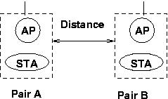
To demonstrate how partially overlapping channels can be used to improve reuse of the RF spectrum, we consider the following setup. Two APs and two stations (STA), with one STA associated to each AP, take part in the experiments. One such AP-STA pair, called Pair-A, is kept fixed at a particular location within an office building, while the other Pair-B is moved to various different locations of measurement. The distance between an AP and its associated STA is kept constant throughout the experiment process.
The following parameters are varied to study the effect of using partially overlapping channels on TCP/UDP throughput and MAC level collisions: The distance between the AP-STA pairs is varied to study the interference range of the BSS formed by the pair. The datarate used for communication was chosen from the following permissible instantaneous data rates: 2, 5.5 and 11 Mbps (note, throughputs will be lower). The channel separation, which refers to the difference in the channel numbers used by the two pairs, is varied between 0 and 5. For each selection of the parameters, we monitored TCP and UDP throughputs for flows lasting 10 seconds. The MAC level collisions were also monitored. All APs and STAs used wireless NICs from the same vendor with a constant transmit power of 30mW.
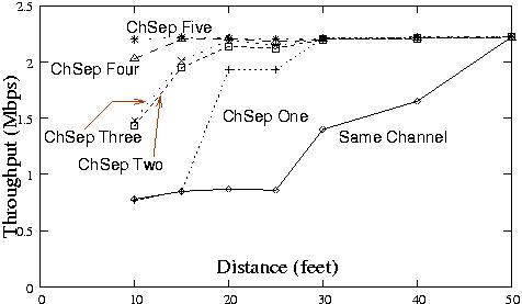
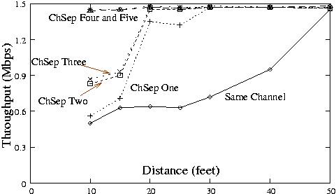
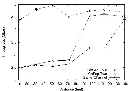
Figure 3(a) plots the UDP throughput achieved by the AP-STA Pair-B against distance from Pair-A. This experiment used a datarate of 2 Mbps which best shows how a step by step decrease in overlap increases the AP-STA throughput (other datarates omitted due to space restrictions). Figure shows that using the same channel, a distance of around 50 feet would be necessary to eliminate the interference and attain the maximum possible throughput. This throughput is attained for much smaller distances as the channel separation (indicated by the legend ChSep) is increased from 0 (same channel ) to 5 (non-overlapping channels). Figure 3(b) shows the same effect on TCP throughput. Figure 3(c) shows the TCP throughput in a second environment, which is an office building with a long corridor on which the experiments were performed. The datarate here was set at 11 Mbps.
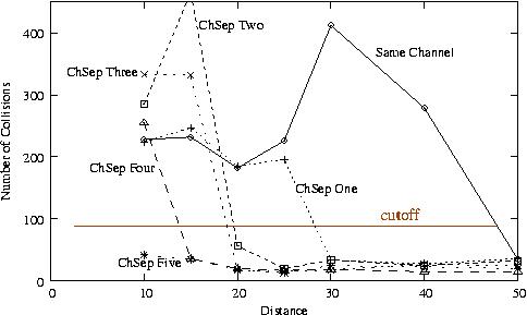
Figure 5 shows the number of collisions that occurred at the AP-STA Pair-B. The number of collisions have a significant amount of variation from one execution of the experiment to another because of the randomness present in the MAC protocol. However, clearly noticeable is the fact that a drastic reduction in the number of collisions (as shown by the cutoff at around 100 in Figure 5) indicates significant reduction in interference. Thus, the points at which each curve takes a plunge below the cutoff line (shown in the figure) indicates the distance at which interference does not occur between the two AP-STA pairs.
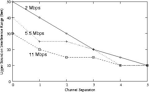
Figure 6 shows the effect of the 802.11 MAC datarate on the interference range of a BSS. Each point on a curve plots the minimum observed distance (modulo discrete observation points) on the y-axis at which with the given channel separation (x-axis) the two AP-STA pairs do not interfere with each other and attain the maximum possible TCP/UDP throughput - which is the interference range of the BSS formed by an AP-STA pair. One observes that for all three datarates, the interference range decreases consistently. Also as expected, for a given amount of channel overlap, a higher datarate has a smaller interference range.
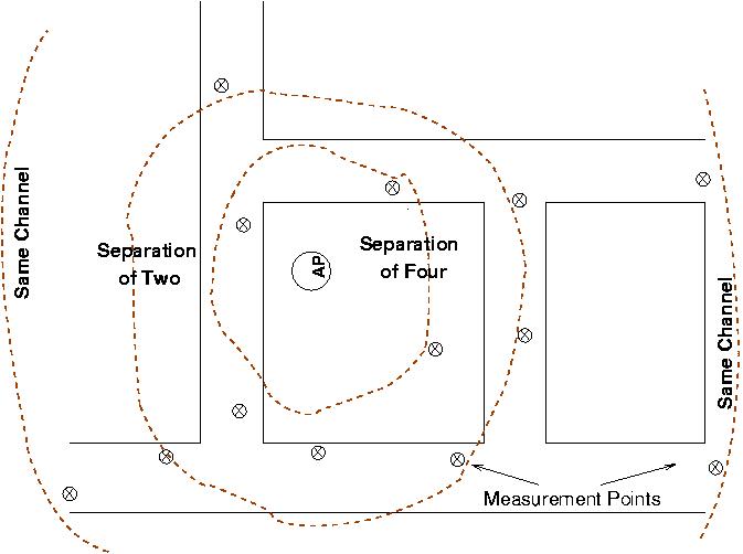
Figure 7 shows graphically the interference ranges for channel separation of zero (same channel), 2 and 4 at a datarate of 2 Mbps. This visually demonstrates how spatial reuse can be significantly improved by carefully employing partially overlapping channels.
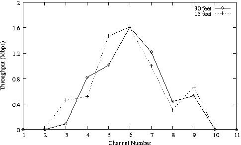
We conduct the following simple experiment: Two nodes are placed on channels with decreasing overlap, and the UDP throughput is measured. One node was kept fixed on channel 6, while the other was progressively moved from channel 1 through 11. The nodes were configured at a datarate of 2Mbps. Figure 8 shows the plots at distances of 15 and 30 feet between the two nodes. The plots demonstrate how a partially overlapping channels can be used to communicate at the cost of reduction in the throughput. This allows a node with a single interface to communicate with nodes on two non-overlapping channels by operating on a channel that partially overlaps with both.
 |
 |
Throughput improvements using partially overlapping channels:
Apart from utilizing partially overlapping channels for topology flexibility in mesh settings,
they can be applied to improve the throughput capacity of multi-hop networks.
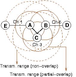
Consider the multihop setup shown in Figure 9. There are
four nodes; each with a single radio interface. Because of this limitation, technically
the network can utilize only one channel or the network would get partitioned. Say, nodes
A, B and C are within communication range of each other. Nodes D and E are each within communication
range of nodes A,B and C. The transmission ranges of nodes A,B and C are shown using
dashed circles. With all nodes operating on a single channel to prevent network partition,
each node shares the channel with two other nodes, thus achieving
roughly ![]() rd of the maximum available bandwidth on one channel.
rd of the maximum available bandwidth on one channel.
Now, using partially overlapping channels, an assignment can be performed
as follows. Nodes A and E are assigned channel 1; nodes B and D are on channel 6. These links
do not interfere with each other. Node C is be placed on channel 4, which allows communication
with both A and B. Channel 4 is chosen such that the reduction in the communication range
as determined by the extent of overlap between
![]() and
and
![]() allows communication with both A
and B. The network thus utilizes the maximum bandwidth available on two non-overlapping channels and hence this can result in significant
throughput improvements.
allows communication with both A
and B. The network thus utilizes the maximum bandwidth available on two non-overlapping channels and hence this can result in significant
throughput improvements.
Through testbed measurements we have evaluated how partial overlap in channels can be exploited for improved spatial re-use (WLANs) and the ability to do multi-channel communication (Mesh). The focus of this paper has really been to add a new mechanism to our toolkit for spectrum management -- partially overlapped channels. We believe this paper is merely the first step towards design of new and efficient algorithms that are aware of the potential demonstrated. In particular it would be possible to re-visit each channel assignment technique designed in the past and examine how they can be extended by employing this new mechanism.
This document was generated using the LaTeX2HTML translator Version 2002 (1.62)
Copyright © 1993, 1994, 1995, 1996,
Nikos Drakos,
Computer Based Learning Unit, University of Leeds.
Copyright © 1997, 1998, 1999,
Ross Moore,
Mathematics Department, Macquarie University, Sydney.
The command line arguments were:
latex2html -split 0 -show_section_numbers -local_icons adjchannel-pdf.tex
The translation was initiated by Arunesh Mishra on 2005-08-11