


Next: Preliminary Conclusions
Up: Privacy-Aware Location Sensor Networks
Previous: Design Considerations
Subsections
A network is needed that provides near real-time location information with the properties that it preserves k-anonymity with respect to the described attack model while still delivering useful data. To achieve this goal, we take the following approach.
- Data cloaking.
- The sensor network perturbs the sensed location data so that it meets the k-anonymity criterion. Ideally, the network applies only the minimum necessary perturbation so that the data retains its usefulness for a large number of applications.
- Hierarchical aggregation.
- Network nodes organize distribution of sensed location data through a spanning tree. Multiple nodes throughout the spanning tree, the coordination leaders (CL), cloak data so that no single entity has a complete view of the original data. The hierarchy should reflect the spatial characteristics of the area. For example, it could be organized into cubicles, rooms, floors, and buildings.
- Secure and unobservable communications.
- Nodes communicate with encrypted and authenticated data packets (e.g., using the SPINS protocols [20]) to prevent eavesdropping and active attacks. In addition, data transmissions are periodic and independent from sensor readings to protect against traffic analysis.
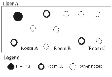
The decentralized cloaking and aggregation mechanism requires one coordination leader for every level of hierarchy; for example, one CL for every room, for every floor, and for the building. Figure 1 depicts such a configuration. All data flows from the individual nodes first to the room CL and then to the floor CL, which sends the data to a location server. Since CLs can be outside the single-hop radio range, network nodes need to establish routes to higher-level coordination leaders. The node routing tables will hold an entry for each of the hierarchical CLs that this node belongs to. Referring to Fig. 1, a node in Room B may be required to forward packets to its room CL, while also forwarding packets from Room C bound for the floor CL. For n levels of hierarchy, n routing table entries will be required. Notice that the size of the routing table scales with the total number of hierarchies, rather than the number of nodes in the network.
Figure 1:
The desired result of coordination leader election is one CL at each hierarchical level
 |
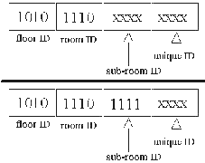
A hierarchical node ID assignment that mirrors the characteristics of the physical area simplifies coordination leader election. To this end, the ID describes where the node is physically located (e.g., in which room). The node ID is subdivided into several bitfields that determine its identification at every level within the hierarchy. Every node will have a unique ID, but nodes within the same room will share the same room ID, while nodes on the same floor will all share the same floor ID. The IDs and the hierarchy are statically configured during system installation.
Coordination leader election and routing table setup uses a 3-way handshake protocol. The process starts with a root node, such as a base station or the location server to elect coordination leaders for the top level (e.g. floors). The selected coordination leaders than recursively apply the protocol to find CLs for their sublevels until leaders are elected for all levels. The handshake involves the three packet types CL_REQUEST, CL_REPLY, and CL_CONFIRM, which simply contain the sender and receiver node ID, a hop count, and the packet type.
A CL broadcasts a CL_REQUEST packet to discover subordinate CLs. This packet is flooded through the network, but is dropped at all nodes that are not subordinates of the request CL (this is determined by comparing sender and node ID). For example, when the CL of Floor A sends out a CL_REQUEST, nodes on Floor B would drop the packet. As this packet is propagated through the network, nodes can set up routing tables to the originating CL. Therefore, a CL_REQUEST from a CL at hierarchical level n, will result in filling all the routing tables for level n at all nodes who recognize the sender as their CL.
Every node that receives a CL_REQUEST packet from a parent CL answers with a CL_REPLY packet. This indicates that the replier is a potential candidate to be a CL at the sublevel. Reply packets use the routes to the CL established through the CL_REQUEST packet. The parent CL then chooses as an unique CL for each direct sublevel the quickest replier among all candidates with the lowest hop count. Other metrics such as signal strength for single hop candidates are also plausible. Intermediate nodes forwarding CL_REPLY packets will increment the hop count field. They can also drop packets from same-level nodes, if they have already sent a reply packet that is superior according to the well-known selection metric. As an example, a node in Room B can drop reply packets from other nodes in Room B, if they have a higher hop count than a previously forwarded packet.
Finally, the parent CL sends a CL_CONFIRM packet to each chosen CL, which is flooded until it reaches the new CL. A confirmed CL then restarts the process by sending out its own CL_REQUEST to the next lower level of hierarchies.
Nodes employ two basic techniques to increase anonymity: Provide less spatial accuracy and perturb the count of subjects in the covered area.
In our hierarchical organization, less spatial accuracy can be achieved by omitting a range of the less significant bits of the sender node ID (ID blurring); thus, the two approaches are:
- Cloak ID, provide precise data
- Cloak data, provide precise ID
The data cloaking algorithm combines both approaches. Each node stores the desired anonymity level k, which is preconfigured. If the number of subjects meets or exceeds k the algorithm cloaks data and provides a precise node ID (which describes the area); otherwise, it provides precise data with a cloaked ID.
Data cloaking is achieved through smart rounding. We define the smart rounding function as follows:
y =

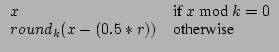
where roundk rounds to the nearest multiple of k and r is a random variable that contains 0 or 1 with equal probability. At higher event counts, smart rounding will allow for more precision of data location, rather than actual data values. Smart Rounding would occur only once if no aggregation occurred with other data packets and then be passed directly up to the highest level.
Having the ID blurred at lower subject counts will allow aggregation of these small numbers to occur at higher hierarchical levels. Eventually the blurred ID will get to a hierarchical level where it can be aggregated and exceeds k. Otherwise, it will get passed up to the highest hierarchical level with that highest level's ID.
In order to defend against traffic analysis attacks, the network will follow a near constant rate of data traffic. Already, nodes are sending events to CLs at a constant rate. Of course, lack of traffic could also possibly give away information. In the office usage space example, lack of traffic would relate to no movement meaning that no one is in the room, floor, or even building. This is information we do not want an attacker to gain. Therefore all nodes are required to send at least one packet per data gathering interval (with an event count of zero). Even if a node has seen no events, it still must send a packet. CLs are also required to send at least one packet.
We require at least one packet, because CLs may have to send multiple packets due to the size of the data incoming versus the buffer size available on the node. By allowing more than one packet to be sent, our design is also much more scalable to larger networks, where data incoming to a node may completely overwhelm the resources available in a node.
Figure 2:
From the lower ID, a receiver would only know an event occurred at the sub-room level. The upper ID shows even more blurring to the room level
 |
Next: Preliminary Conclusions
Up: Privacy-Aware Location Sensor Networks
Previous: Design Considerations
GRUTESER
2003-06-17