


Next: Logical-to-physical Address Mapping
Up: Implementation
Previous: Implementation
Architecture
Figure 6:
The MimdRAID architecture. Shaded
parts are the modules added for an EW-Array.
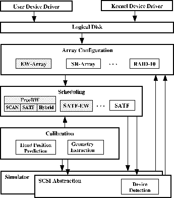 |
The EW-Array prototype is implemented on the ``MimdRAID'' system
developed by Yu et al [30]. Figure 6 shows
how some of the MimdRAID modules have been replaced by
EW-Array-specific components and how these components fit together.
MimdRAID provides a framework and a number of useful features that
enable one to conveniently experiment with novel
disk array designs. We briefly highlight some of these useful
features:

- MimdRAID exports a transparent logical disk interface on Windows 2000 so
that the existing operating system and applications run unmodified on
the underlying experimental disk array.
-
- Highly modularized components of MimdRAID, such as the ``Array
Configuration'' and ``Scheduling'' components of
Figure 6, can be replaced to allow for
experimentation with new array designs.
-
- An accurate software-based disk head position prediction
mechanism (in the ``Calibration'' layer) is crucial for realizing an
EW-Array because the efficient scheduling of both eager-writes and
reads depends on the precise knowledge of the rotational position of
the disk head.
-
- At the lowest layer, the ``SCSI Abstraction'' module, which
manages real Seagate disks, can be substituted with a disk simulator,
so an EW-Array simulator and its implementation effectively share most of the
code. The simulator can shorten simulation time of long traces by
replacing physical I/O time with simulated time; it also allows us to
experiment with a wide range of configurations without
having to physically construct them.
Almost all the EW-Array-specific code in MimdRAID is concentrated in
the Scheduling and Array Configuration layers. The Scheduling layer
implements all the eager-writing scheduling algorithms described in
Section 4. The Array Configuration layer is responsible
for translating requests of logical I/O addresses to those of physical I/O
addresses. This layer maintains a logical-to-physical address mapping
and we describe this next.
Next: Logical-to-physical Address Mapping
Up: Implementation
Previous: Implementation
Chi Zhang
2001-11-16