The ACPI Specification defines three types of components:
When an ACPI-based system is powered up, before the operating system is loaded the ACPI BIOS places the initial ACPI tables in memory. Since the ACPI tables are typically too large to put in the 128KB BIOS memory area, the ACPI BIOS obtains a physical memory map of the system in order to allocate space for the ACPI tables. When an ACPI-aware operating system kernel is started, it search for a small data structure within the BIOS memory area. If a valid structure is found (e.g. if its checksum and signature match) then the kernel uses this structure to obtain a pointer to the ACPI tables and memory map. This information is used by the kernel to preserve the ACPI tables when the virtual memory system is started.
The definition blocks within the ACPI tables are stored in a
hierarchical tree-based name space. Each node in the tree is named.
Node names consist of four capital alphanumeric characters and
underscores (e.g. ``FOO_,'' or ``_CRS''). Namespace
components are separated by periods, and the root of the namespace is
denoted with a backslash (``![]() ''). Names without a leading
backslash are considered to be relative to the current scope in the
name space. Node names that begin with an underscore are reserved by
the ACPI specification for describing features. For example, nodes in
the _SB namespace refer to busses and devices attached to the
main system bus, nodes in the _TZ namespace relate to thermal
management, and nodes in _GPE are associated with general
purpose ACPI events.
''). Names without a leading
backslash are considered to be relative to the current scope in the
name space. Node names that begin with an underscore are reserved by
the ACPI specification for describing features. For example, nodes in
the _SB namespace refer to busses and devices attached to the
main system bus, nodes in the _TZ namespace relate to thermal
management, and nodes in _GPE are associated with general
purpose ACPI events.
Except for the few operations performed by the ACPI BIOS, almost all ACPI operations are performed in the operating system context by interpreting machine-independent ACPI Machine Language (AML) byte-code stored in the ACPI tables. These blocks of AML are called methods. AML methods are stored in specially named nodes in the ACPI namespace. For example, the name _PS0 is reserved for storing AML methods that evaluate a device's power requirements in the ``D0'' state (device fully on). Thus the node _SB.PCI0.CRD0._PS0 contains an AML _PS0 method for the CRD0 device on the system's PCI0 bus.
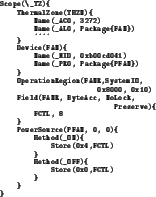
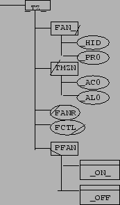
AML is usually compiled from human-readable ACPI Source Language (ASL). Figure 2 shows an example block of ASL code for thermal management that defines four named data elements and two methods. The ``Scope'' operator defines what part of the ACPI namespace the contained block of code resides in. The ``ThermalZone'' operator defines a object representing a region of thermal control. The ``Device'' operator defines a device object, and the ``PowerSource'' operator defines a power switch object. The ``OperationRegion'' and ``Field'' operators are used to define blocks of registers and fields within them, respectively. The ``Name'' and ``Method'' operators define data and program elements belonging to their parent objects. For example, the first ``Name'' in the figure defines _TZ.TMZN._AC0 (the fan high-speed threshold) to be the integer 3272, which means 327.2 K. The ``_ON'' method defined in the figure contains code to turn the fan on. A graphical representation of the namespace defined in Figure 2 is shown in Figure 3.
In the next three subsections we describe ACPI's configuration, power management, and thermal management subsystems.