| ||||||||||||||||||||||||||||||||||||||||||||||||||||
|
USENIX '05 Paper
[USENIX '05 Technical Program]
A Tool for Automated iptables Firewall Analysis
AbstractWe describe ITVal, a tool that enables the efficient analysis of an iptables-based firewall. The underlying basis of ITVal is a library for the efficient manipulation of multi-way decision diagrams. We represent iptables rule sets and queries about the firewall defined by those rule sets as multi-way decision diagrams, and determine answers for the queries by manipulating the diagrams. In addition to discussing the design and implementation of ITVal, we describe how it can be used to detect and correct common firewall errors. 1 IntroductionAs firewalls have become a cornerstone of many security policies, they have grown in power and in complexity. In addition to packet filtering, a typical firewall now provides stateful inspection and packet mangling. One side effect of these changes is the increasing difficulty of correctly configuring a firewall rule set. Subtle errors in a firewall configuration can be difficult to detect, but can open the doors to a malicious intruder or a denial of service attack. Integrated into the Linux kernel is a firewall system called netfilter[16,13,4], which provides the internal hooks for the iptables packet filter. Both stateful inspection and advanced packet mangling are supported by iptables. To configure iptables, a system administrator creates chains of filtering rules in which order is significant. This means that inserting rules in the wrong order can introduce errors. Additionally, because the number and size of the chains determines the complexity of the rule set, a firewall with many large chains can be very difficult to understand. Sometimes it is difficult even to know which requests for important network services are allowed to pass through the firewall filter. Configuration errors can be extremely difficult to identify in a real world system. Figure 1 shows a firewall that secures an internal network 192.168.2.0/24 from intrusions by hosts on an unsecured wireless network 192.168.1.0/24. All traffic, including HTTP traffic, should be dropped from that insecure network. Rule 1 drops any incoming ICMP packets. Rule 2 drops traffic from the insecure network. The remaining rules secure various services and let in traffic to the web server. All other traffic is dropped, unless it comes from a secure subnet 113.192.10.0/24. Let's say the administrator decides to modify this configuration to allow IPP printing traffic (port 631) from trusted machines to pass through the firewall to the secure network. If she inserts an accept rule in the wrong place, she can produce the incorrect configuration in figure 2. This configuration allows printing service from the insecure network, because the new rule has been inserted before the rule which restricts the insecure subnet. Switching rules 2 and 3 yields a correct configuration. This sort of error becomes harder to detect as the number of rules grows and the complexity of their structure increases.
against intrustions from untrusted network 192.168.1.0/24
Consider also the firewall rule set described in figure 3, which protects an internal subnet 192.168.2.0/24 from the outside world. Can mail be forwarded through this filter from an arbitrary host using SMTP? The answer is yes. At first glance, it appears that only hosts from 192.168.2.0/24 can access SMTP (they are granted access in rule 5). Rule 6, however, gives access to any host on any port, provided it is part of an established connection. In order for SMTP traffic to pass from an outside host through the firewall, one of the machines in the 192.168.2.0/24 subnet must establish an SMTP connection to the unauthorized host. Once a connection has been established (via TCP handshake), rule 6 will allow arbitrary access. This scenario could happen if an internal machine is compromised by a virus or Trojan. It could then open up a mail server, connect to the external host, and forward spam to anyone on the internal network.
While these errors can easily be avoided by a careful system administrator, far more subtle and complicated errors can evolve as a firewall rule set grows and is modified to permit new services or patch new security vulnerabilities. In a survey of 37 corporate firewalls, Wool[18] discovered an average of 7 configuration errors per system. While his study did not examine iptables systems, it is not unreasonable to assume that the error rate for Linux systems is comparable to those of Checkpoint firewalls. In [2], Alexander points out that because firewalls are hard to configure, they often fail to prevent spoofing attacks from one internal subnet to another, which can compromise vital financial and planning information. 1.1 Existing ToolsThere have been several different attempts to address the problem of firewall misconfiguration. These solution can be broken into two basic categories: active testing and passive testing. Active testing uses tools such as SATAN[9], nessus[3], or Ftester[5] to subject a firewall to a sequence of carefully crafted packets and see which ones get through. Passive testing involves an offline analysis of the firewall configuration. Since it is impossible to test every possible packet, active tools test only a portion of the firewall configuration. This makes them well-suited for detecting specific vulnerabilities and for detecting implementation bugs in the firewall software, but not for generating trust in the overall security of a firewall configuration. It also means that testing can interfere with normal network activity. The current state of the art in passive analysis is a commercial tool produced by Algorithmic Security called "Algosec Firewall Analyzer", which is available for PIX and Checkpoint FW-1 firewalls. It is a closed-source commercial project based on Wool's Fang[1] and Lumeta[17] engines. Fang allowed the user to perform simple queries such as "what packets can reach the mail server." In Lumeta, the developers replaced Fang's query functionality with a graphical tool that checks for specific configuration errors. Algosec is a more powerful commercial version of Lumeta. Each of their systems is capable of analyzing multiple firewalls in a specified network topology. Another branch of research has focused on simplifying a firewall configuration by removing redundant and conflicting rules. In [10], Gouda and Liu present an algorithm for constructing a firewall decision diagram and applying reduction techniques to derive a complete, compact, and consistent firewall. Their technique can reduce the complexity of a poorly configured firewall and uncover some configuration errors, but has a different purpose than such engines as Algosec and SATAN. Gouda and Liu's work focuses on errors in the structure of a firewall rule set rather than its substance. None of these techniques is widely available in an open source tool which can be used with iptables. An interesting intermediary between active and passive tools is Russell's netfilter simulator[14]. The simulator is intended to be used for debugging kernel hooks in netfilter, and provides very low-level access to the internals of netfilter, so it is not by itself suitable as a query tool for non-developers, but could perhaps be used as the basis of a more general query library. 2 ITVal, An Open Source ToolIn this paper, we present ITVal, an open-source firewall analysis tool for iptables. The tool takes as inputs a firewall rule set as generated by the output of the "iptables -L -n" command and a query file written in a simple language we describe in section 3. It then calculates the set of packets which can be accepted by the firewall and produces the answers to each query in the query file. In the query file, the user can ask questions such as "What services can be reached on host X?" or "Which machines can be reached with SSH?" The analysis engine resolves the queries using a very efficient decision diagram data structure and prints the results on standard output. The analysis engine can handle many of the features of iptables, including stateful inspection. Using this tool, the system administrator can check important security properties before and after making a change to the firewall. If the query engine returns an unexpected result, he can examine his changes for errors and reapply the security check. The analysis engine is implemented using FDDL[12], a Multi-way Decision Diagram (MDD) library. We chose to use MDDs[8] over Binary Decision Diagrams(BDDs)[6] because they are better suited for representing integral values such as ports and IP address. Decision diagrams have been previously used to represent firewall rules. In [15], Hazelhurst et al. showed that firewalls could be represented using Binary Decision Diagrams and implemented a limited number of queries using formal logic. In [11], they shifted their focus toward improving firewall performance by representing the rule set using decision diagrams. Christiansen and Fleury took this a step further in [7] by implementing an Interval Decision Diagram based packet filter for use with netfilter. These projects, and that of Gouda cited above, have a different motivation from that of ITVal. While these projects sought to enhance performance and provide a formal characterization of firewall rule sets, our aim is to provide a simple, plain English query language that simplifies accurate firewall configuration. 3 Query Language
The analysis tool provides a straightforward query language which allows complex queries to be built from simple primitives. An example query file is shown in figure 4. The query file consists of a set of group and service definitions followed by one or more query statements. The first four lines of figure 4 are definitions. The next four lines are query statements. 3.1 Query StatementsQuery statements begin with the word QUERY followed by a subject, an optional input chain, a condition, and a semicolon. The subject of the query specifies what information should be printed about packets that match the query. For instance, in line 5, the subject "DADDY" indicates that the destination address should be printed. The valid subjects are:
A query statement can optionally contain the name of an input chain to use. The input chain must be one of the three built-in chains: INPUT, FORWARD, or OUTPUT. If no input chain is explicitly given, the analysis engine assumes that the FORWARD chain should be considered. Line 6 of the example specifies that the OUTPUT chain should be considered rather than the FORWARD chain. The rest of the query statement consists of a condition which specifies the packets to consider. 3.2 Simple ConditionsThe query engine allows the user to build complex conditions out of very simple conditions. Conditions are built from seven simple primitives:
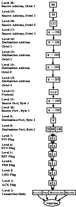
Each of the primitives selects those packets that are accepted and that match the specified criteria. For instance "FROM 127.0.0.1" specifies those packets accepted by the firewall which are outbound from localhost. For the FROM and TO queries, the address group can either be the name of a predefined address group or the numeric IP address of a host. Asterisks may be used in numerical addresses to describe an entire subnet at once. For the ON and FOR queries, the service can be either the name of a predefined service or the numeric port number of the service preceded by the protocol type. An asterisk can be used to match all packets of the given protocol type. The protocol type can either be TCP, UDP, BOTH, or ICMP. If ICMP is chosen, the ICMP packet type number should be specified instead of a numerical port. If BOTH is specified, the analysis engine will match both TCP and UDP packets. For the WITH primitive, the recognized TCP flags are URG, PSH, RST, FIN, SYN, and ACK. For the IN primitive, the connection state can be either INVALID, NEW, ESTABLISHED, or RELATED. The LOGGED primitive stands on its own without any parameters. It indicates that a packet may have been logged by the firewall. Since iptables LOG rules can specify time-related and other external criteria for logging, there is no guarantee that every matching packet will actually be logged. 3.3 Complex QueriesThe boolean connectives NOT, AND, and OR allow the user to posit queries of arbitrary complexity. These operators work as one would expect. "NOT FROM TCP 21" matches against all accepted packets which are not TCP packets on port 21. "FOR mail OR FROM 127.0.0.1" selects both mail packets and packets outbound from localhost. Parentheses may be used to disambiguate subexpressions containing multiple operators. 3.4 Group and Service definitionsIf the user had to explicitly mention every host address explicitly in every query, creating a query file would be a tedious and error prone process. To address this issue, we allow named groups of addresses to be defined and used throughout the query file. The syntax for specifying a group is the word GROUP followed by a name and a space separated list of addresses. Asterisks may be used to include entire subnets at once. Group names must consist entirely of letters and may not match any keyword of the query language. Similarly, named groups of services may be defined. The syntax for defining a service is the word SERVICE followed by a name and a space separated list of protocols and ports. 4 ImplementationWhen invoked on an iptables rule set as given in the output of iptables -n -Land a query file, the ITVal analysis engine parses the rule set and builds an MDD representing the set of packets accepted by the firewall for each of the built-in chains. Then it parses the query file and generates an MDD representing the set of packets which match the condition of each query. Using an efficient MDD intersection operator, it calculates the set of packets that are both accepted by the firewall and match the condition of the query. Then it displays the information specified in the subject of the query. 4.1 Using Decision DiagramsA multi-way decision diagram(MDD) is a directed acyclic graph in which the nodes are organized into K+1 levels and all arcs from a node at non-terminal level k > 0 point to nodes at level k-1. In this application, every path through the MDD represents a packet potentially received by the firewall. Each of the non-terminal levels of the MDD corresponds to a specific attribute of the packet. For instance, in figure 5, the MDD corresponding to the rule set of figure 1, level 20 represents the first octet of the source address. 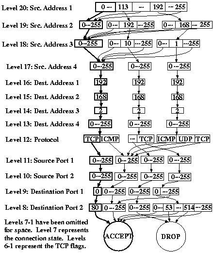
Level 0 is a special terminal level which, for rule set MDDs, represents the target of the firewall rule (ACCEPT, DROP, LOG, or a user-defined chain) as a unique integer index. We also reserve terminal index 0 to mean "not yet specified." For the query MDDs, nodes at the terminal level express whether or not the packet matches the query criteria. Terminal node 0 represents "does not match" and terminal node 1 represents "matches". A non-terminal node at level k represents a subset of packets that share some attributes. An arc from a node at level k to a node at level k-1 represents a choice of value for the attribute represented at level k. When many arcs from a node point to the same child, we use ellipses in the figure to save space. In the actual MDD there would be arcs for each value we have hidden in this manner. Nodes at each level are stored in a dynamic array and are referenced by a unique integer index. At every level, we reserve index 0 for a special node, node zero, which represents the empty set. This can be thought of as a node with all its arcs pointing to node zero at the level below. To save a small amount of memory, we do not explicitly store node zero. We denote node n of level k as < k,n > and the ith arc of that node as < k,n > [i]. To see that an HTTP packet from 68.10.1.3 to 192.168.2.10 is accepted by the firewall, start with the node at level 20 of the MDD. Since the first source octet of the packet is 68, which falls between 0 and 113, follow the first arc to the highlighted node at level 19. Now there is only one arc to follow. Since 10 falls between 0 and 255, follow the highlighted arc to the next level. Again, 1 falls between 0 and 255 so follow the arc to level 17. The last octet of the source address is 3, which falls between 0 and 255, so follow the highlighted arc to the node at level 16. Level 16 represents the first octet of the destination address, which for our example is 192. Since there is an arc for 192, proceed to level 15. If the destination address had been 193.1.1.1, you would know that the packet is dropped by the firewall, since there is no arc for 193 and DROP is the default policy. Instead, at level 15, examine the second octet of the destination address. Since there is an arc for 168, proceed to level 14. Continue in this manner to level 12. At level 12, there is an arc for TCP and an arc for ICMP. Since HTTP is a TCP protocol, follow the arc for TCP to the highlighted node at level 11. Continue in this manner until you reach the node at terminal level 0. Since it is the ACCEPT node, the packet will be accepted by the firewall. 4.2 Building an MDD for a Filter Rule
In order to construct an MDD for a rule, we first parse the rule into target, source address, destination address, source port, destination port, protocol, state, and flag components. From these components, we create a parsed rule, which represents each component as an integer. We define an operation MakeMDDFromRule, show in figure 6, which takes the parsed firewall rule and returns the root node < K,n > of an MDD representing that rule. The algorithm starts at level 0 and builds upward toward the root node. At each level, it creates new nodes that represent the criteria of the parsed rule. In line 1, Node < 0,n > is determined directly by finding the equivalent integer index of the rule target. For ACCEPT, DROP, and LOG targets this is a predefined constant less than 4. For user-defined rules, the index comes from a pre-generated table that maps the user-defined chains, in the order of their discovery during parsing, to integers greater than 3. Lines 2-7 construct nodes at levels 1 through K. The call to NewNode in line 3 creates a new node and initializes all its arcs to point at node zero. Lines 4-7 examine each potential value i of filter rule attribute k. If i falls within the range specified by the parsed rule, arc < k,n > [i] is connected to node < k-1,old >. Otherwise, the arc is left at its default value, which points to node zero. In line 7, we have considered all the potential values of attribute k, so we now call CheckForDuplicates, which uses hashing to identify any nodes that exactly duplicate node < k,n > . If such a node exists, < k,n > is freed and CheckForDuplicates returns the index of the duplicate node. Otherwise, it returns < k,n >. 4.3 Converting chains to MDDs
In order to construct the MDD for an entire rule set, we consider chains using the algorithm shown in figure 7. To simplify this discussion, we omit the handling of LOG rules from the algorithm. LOG rules are implemented by maintaining an additional MDD for each chain which describes the set of logged packets. The algorithm, ConvertChain, takes as inputs a chain, represented as a linked list of parsed rules, and an MDD storing the set of packets accepted by the rules seen so far. It recursively traverses the chain one rule at a time (in reverse order) to build an MDD representing the entire chain. We initially call ConvertChain by passing in the first rule of the parsed FORWARD, INPUT, or OUTPUT chain and an MDD describing the default policy. This initial MDD consists of a single node, < k,n > , at each level. All arcs of the node at level 1 point to the index of the default target. All arcs of the nodes at levels k > 1 point to node < k-1,n >. Lines 1 through 3 of ConvertChain place the rules of the chain on the call stack so that the rules can be processed in reverse order. The algorithm traverses the linked list until it reaches the end and then returns so that tup points to the last rule of the chain. Line 4 creates an MDD representation of the rule as described in section 4.2. If the rule is a simple ACCEPT or DROP rule, line 6 uses a Replace operator to mask the new rule over any existing rules in the chain. Pseudocode for Replace is shown in figure 8.
Replace descends the MDD recursively, starting from the root node. When it reaches a terminal node, it returns node < k,q > if < k,p > and < k,q > are both non-zero. Otherwise, it returns < k,p >. Calling Replace on inMDD and interMDD produces a new MDD in which every rule of interMDD masks any matching rule in inMDD. Lines 8-11 of ConvertChain handle the case where the target of the new rule is a user-defined chain. In line 9, an MDD representing the criteria portion of the rule is created using a recursive call to ConvertChain. Because iptables does not allow cyclic references in chain targets, the recursion is guaranteed to terminate. When we return from the recursion, the ACCEPT and DROP rules of the user-defined chain will have been applied to our intermediate MDD, but some paths through the MDD may still lead to the chain-name target. These paths represent packets that are unaltered by the chain. We mask these out in line 10, and use the Replace operator to mask the new MDD over the result. The MDD created by ConvertChain must only affect packets that match the criteria for the rule under consideration. The target chain, however, may have more general rules that affect packets that do not match those criteria. To avoid this problem, the replace operator only modifies packets that do not map to the "unspecified" terminal, terminal 0. Since the default policy matches every packet to some terminal, this will always be the case when applying ACCEPT and DROP rules to the top-level chain. When applying rules to a target chain, however, rules outside the criteria under consideration will map to 0 and be ignored by the replace operator.
4.4 Resolving QueriesThe MDD for a query condition is constructed by joining smaller MDDs together according to the structure of the query. The MDD for a primitive, such as FROM, is built in the same manner as the MDD for a rule which matches every packet specified by the operator. Instead of ACCEPT, however, the terminal node is "matches". The primitive MDDs are then joined using an MDD union and the MDD intersection operator in figure 12 to produce the final query condition. The union operator is derived directly from the intersection operator by modifying the base cases. The function MaxValue returns the maximum value for the field associated with level k. For instance, the maximum value of level 20 is 255, since level 20 represents the first octet of the source IP address. A cache is used to improve performance. Without the cache we might need to compute the intersection of a pair of nodes several times. Using the cache, we are guaranteed to compute it only once.
In order to resolve a query, we use FDDL to compute the intersection of the query MDD and the rule set MDD. The intersection algorithm for combining a query MDD and a rule MDD differs only slightly from the intersection operator used to combine query MDDs. The modified intersection algorithm replaces lines 1-3 of figure 12 with those in figure 11 and produces an MDD which represents those packets that both satisfy the query and are accepted by the iptables rule set. The intersection operation is linear in the product of the number of nodes in each MDD. Since the number of nodes can be exponentially smaller than the number of possible packets, queries can be performed very rapidly.
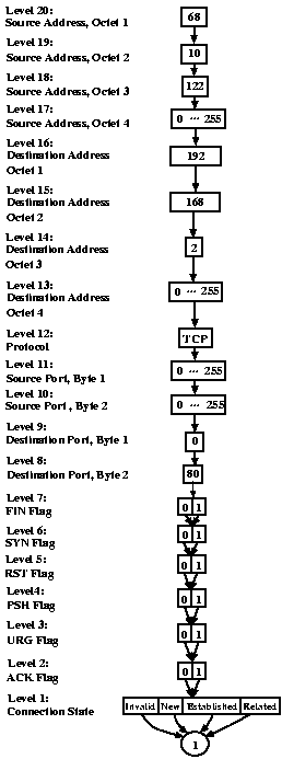
The result of intersecting the MDDs in our running example is shown in figure 10. To see which packets are represented by the MDD, we start with the node at level 20. This node has a single arc representing the value 68, so all packets in the result have a source address that begins with 68. Following the arc, we reach another node with a single arc. This node represents all packets with second source octet equal to 10. Continuing in this manner, we realize that the source address of all packets in the result must be in the group 68.10.122.* and the destination address must be in the group 192.168.2.*. The protocol must be TCP and the source port can have any value, but the destination port must be port 80, the HTTP port. When we continue down the graph, we realize that the result contains packets with any TCP flag condition and in any connection state. In other words, the result of our query is exactly: all HTTP packets from 68.10.122.* to 192.168.2.*. i In the context of ITVal, the output of the sample query applied to the sample rule set is shown in figure 13. Note that the human-readable output corresponds directly to the output MDD of figure 10.
5 Using ITVal
To illustrate how a hypothetical system administrator might use ITVal to detect and correct configuration errors, we return to the rule set described in figure 1. The query file shown in figure 14 can be used to verify all the important assertions about this network. For instance, the first query lists all services which can be accessed by the wireless network. The result of this query should be the empty set, since we want to restrict all access from that network. Similarly, the last query lists all hosts not on the wireless network that can access a service other than those explicitly permitted or denied. Only hosts from the trusted 113.192.10.0/24 network should appear in the answer to this query.
Running ITVal on the initial configuration gives the output shown in figure 15. In order to save space, we have grouped the output of the fourth query into ranges. The actual output would explicitly list each distinguishable subnet. It is easy to verify that all the requirements are satisfied. Suppose the administrator makes the incorrect change shown in figure 2. Running ITVal on this new rule set produces figure 16.
Because the first query no longer produces an empty result, it is evident that this rule set is incorrect. Realizing her mistake, the system administrator can then move the rule to its correct location in the rule set. Now the output of the first query will once again be the empty set. 6 ConclusionUsing ITVal, a system administrator can quickly and easily verify that their firewall system important security requirements. One advantage of the query language is that generic queries generated for one firewall system can be employed on another firewall system with few modifications. This means that even without a complete understanding of the query language syntax, a system administrator can use ITVal to check fundamental security properties. Furthermore, queries are easier to generate correctly than the firewall rule sets, because they are more general, not order dependent, and don't depend on a complex interaction between independent chains. There are a few areas in which ITVal needs further development, however. First, several types of packet mangling, such as masquerading and NAT, should be supported. Second, to enhance the applicability of the tool to real systems, it needs a mechanism for composition of firewalls in an arbitrary topology. Third, the tool needs a better output mechanism that can display results more concisely and allow the user to specify query subjects containing multiple fields. Currently, queries that generate a large number of results can be difficult to interpret. A better interface could hide or group irrelevant data so that critical information stands out more clearly. In the long term, a graphical or interactive interface for displaying output would be a logical step. The tool, as currently described, is available at https://www.cs.wm.edu/~rmmarm/ITVal/. References
| ||||||||||||||||||||||||||||||||||||||||||||||||||||||||||||||||||||||||||||||||||||||||||||||||||||||||||||||||||||||||||||||||||||||||||||||||||||||||||||||||||||||||||||||||||||||||||||||||||||||||||||||||||||||||||||||||||||||||||||||||||||||||||||||||||||||||||||||||||||||||||||||||||||||||||||||||||||||||||||||||||||||||
|
This paper was originally published in the
Proceedings of the 2005 USENIX Annual Technical Conference,
April 10–15, 2005, Anaheim, CA, USA Last changed: 3 Mar. 2005 aw |
|