|
NSDI '05 Paper
[NSDI '05 Technical Program]
Using Emulation to Understand and Improve
Wireless Networks and Applications
Glenn Judd and Peter Steenkiste1
Carnegie Mellon University
Pittsburgh, PA, USA
glennj@cs.cmu.edu prs@cs.cmu.edu
Abstract
Researchers have long faced
a fundamental tension between the experimental realism
of wireless testbeds on one hand, and the control and
repeatability of simulation on the other hand.
To overcome the stark tradeoff of these traditional
alternatives, we are developing a
wireless emulator that enables both realistic and repeatable
experimentation
by leveraging physical layer emulation.
We discuss the design and implementation of a prototype
wireless emulator, and show how this emulator can
be leveraged to provide insight into wireless network
and application behavior.
Our experience shows that, compared to simulation,
our emulator-based approach provides us with a better
understanding of real-world wireless network performance, and enables
us to quickly deploy our research into an operational
wireless network, while still allowing us to enjoy the benefits of a
controlled experimental environment.
1 Introduction
As wireless network deployment and use become ubiquitous, it
is increasingly important to make efficient use
of the finite bandwidth provided.
Unfortunately, research aimed at evaluating and improving
wireless network protocols and applications is hindered by
the inability to perform repeatable and realistic experiments.
Experimental techniques that have proven successful for
wired networks
are inadequate for wireless networks
since a wireless physical layer fundamentally affects
operation at all layers of the protocol stack in complex ways.
Links are no longer constant, reliable, and physically isolated from
each other, but are variable, error-prone, and share a single
medium with each other and with external uncontrolled sources.
An ideal method of wireless experimentation would possess
the following properties:
repeatability and experimental control,
layer 1-4 realism,
the ability to run real applications,
configurability,
the ability to modify wireless device behavior,
automation and remote management,
support for a large number of nodes,
isolation from production networks,
and integration with wired networks and testbeds.
We now discuss how alternative methods of experimentation
fare with respect to this list of desirable properties.
The most direct method of addressing realism is to conduct
experiments using real hardware and software in various
real world environments. Unfortunately, this approach faces
serious repeatability and control issues since the behavior of the
physical layer is tightly
coupled to the physical environment and precise conditions
under which an experiment is conducted. The mobility of
uncontrolled radio sources, physical objects, and people makes these
conditions nearly impossible to reproduce. Even repeating the
same experiment twice can be a daunting task when anything in
the surrounding environment is in motion; remote researchers
face an even bleaker situation trying to reproduce an
experiment.
It is also
difficult to avoid affecting colocated production networks.
Moreover, configurability and management of even a small number
of mobile nodes distributed in three dimensions is cumbersome.
For these reasons, many researchers have understandably
embraced simulation.
This approach solves the problems of repeatability,
configurability, manageability, modifiability, and
(potentially) integration with external networks,
but faces formidable obstacles in terms of realism.
Wireless simulators are confronted with the difficult
task of recreating the operation of a system at
all layers of the network protocol stack as well as the interaction
of the system in the physical environment.
To make the problem tractable, simplifications are
typically made throughout the implementation of the simulator.
Even fundamental functions such as deciding what a received frame looks
like [1] diverge greatly from the
operation of real hardware. Evaluating real applications running
over wireless networks is typically very difficult
using a simulator.
In addition, while wireless technology is undergoing rapid advances, wireless
simulators, in particular open source wireless simulators, have lagged
significantly behind these advances as discussed in Section 7.
The aforementioned issues with simulators, and a desire to
avoid long simulation times, have caused some researchers to
adopt emulation as a means of evaluation. Emulation retains
simulation's advantages of repeatability and manageability,
while potentially mitigating the issue of realism.
Unfortunately, as discussed in Section 7,
most emulators have
adopted extremely simplified MAC and physical layers.
As the operation of these layers is fundamental to the operation
of a wireless network, it is unclear that these emulators gain
any realism over existing simulators.
We are developing a wireless emulator
that enables both realistic and repeatable wireless experimentation
by accurately emulating wireless signal propagation in a physical
space. Unlike previous approaches, this emulator utilizes
a real MAC layer, provides a realistic physical layer, and supports
real applications while avoiding
adopting an uncontrollable or locale-specific architecture.
The key technique we use to accomplish this is
digital emulation of signal propagation using an FPGA.
Our emulator's high degree of control and fidelity allow
signal propagation to be modeled in several ways:
first, widely used statistical models of signal propagation
can be used; in addition, traces of observed signal propagation
can be "replayed" on our emulator; lastly, manual
control of signal propagation can be used to analyze
behavior in artificially created situations that would
be difficult or impossible to reproduce in an open system.
Section 4 will discuss signal modeling
in more detail.
This emulator provides an attractive middle ground between
pure simulation and wireless testbeds. To a large degree,
this emulator should be able to maintain the repeatability,
configurability, isolation from production networks,
and manageability of simulation
while retaining the support for real applications and much of the realism of
hardware testbeds. As a result, this emulator
should provide a superior platform for wireless experimentation.
This emulator is not,
however, a complete replacement for simulation and real world
evaluation. Simulation is still useful in cases where
a very large-scale experiment is needed or in certain cases
where functionality not available in hardware is required
(e.g. changing the MAC firmware).
Real world evaluation is still useful when radio channel fidelity
beyond the capabilities of the emulator is required,
or for verifying the operation of the emulator in
real-world settings.
In this paper we present the design of a physical-layer
wireless emulator. We introduce the architecture of
this emulator in Section 2.
In Section 3 we discuss an initial
proof-of-concept prototype, and our
partially complete implementation of a "Version 2"
emulator based on this proof-of-concept.
Section 4 discusses how our emulator
can be used to emulate various signal propagation environments.
Using both the prototype and the Version 2 emulator,
we present several experiments in Section 5
and a case study in Section 6
that demonstrate the power of our approach.
Section 7 discusses related work,
and Section 8 concludes our discussion.
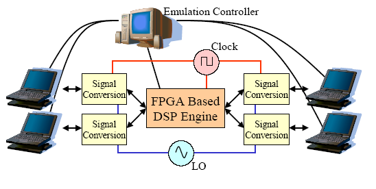
Figure 1: Emulator Architecture
2 Emulator Architecture
The architecture of our emulator is shown in Figure 1.
A number of "RF nodes" (e.g. laptops, access points, cordless phones,
or any wireless
device in the supported frequency range) are connected
to the emulator through a cable attached to the antenna port of their
wireless line cards (each RF node corresponds to a single antenna, so
a single device can be represented by multiple RF nodes).
For each RF node, the RF signal transmitted by its line card is "mixed"
with the local oscillator (LO) signal. This shifts the signal down to a lower
frequency where it is then digitized, and fed into a DSP Engine
that is built around one or more FPGAs. The DSP Engine models the effects of
signal propagation (e.g. large-scale attenuation and small-scale fading)
on each signal path between each RF node. Finally, for each
RF node, the DSP combines the appropriately processed input signals from all
the other RF nodes. This signal is then sent out to the wireless line card
through the antenna port.
Given the current state of technology, a DSP Engine based
on a single FPGA might support over 20 wideband RF nodes. Using multiple FPGAs
or lower bandwidth RF nodes, even larger systems can be built.
The operation of the emulator is managed by the Emulation Controller,
which coordinates the movement of RF nodes (and possibly physical objects)
in the emulated physical space. The Emulation Controller uses location information (and
other factors as dictated by the signal propagation model in use)
to control the emulation of signal propagation within
this emulated environment. In addition, the Emulation Controller
coordinates node (and object) movement in physical space with
the operation of RF node applications and sending of data.
Each RF node runs a small daemon that allows the Emulation Controller
to control its operation via a wired network. RF nodes that are not
capable of running code may require a proxy to run the daemon on their
behalf.
Connecting the Emulation Controller to an external network allows
remote management of the emulator. In addition, individual nodes
in the emulator may be connected to external networks in order to
allow emulator nodes access to the Internet at large or to allow
the emulator to be used in conjunction with testbeds such as
PlanetLab [2] or Emulab [3].
 Figure 2: Prototype Hardware Architecture
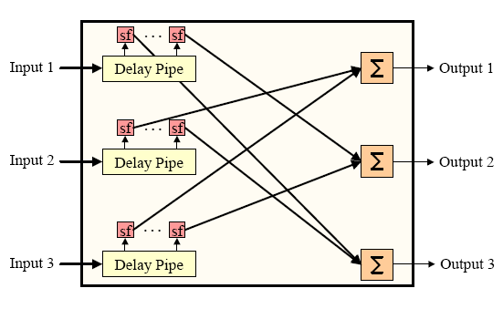 Figure 3: Prototype DSP Engine Operation
3 Implementation
To demonstrate the feasibility of the wireless emulator,
we constructed a small prototype designed to validate
the emulator's primary functionality by emulating signal
propagation between three laptops on a single 802.11b
"non-overlapping channel".
The results obtained with our prototype [4],
in conjunction with MIT's
Roofnet project [5], and
experiments discussed in Sections 5
and 6
show that the approach
we advocate is capable of providing powerful wireless
emulation capabilities.
We first discuss our prototype's
hardware and software implementation, and then discuss
how Version 2 improves on the
capabilities demonstrated by the prototype.
3.1 Proof-of-Concept Prototype
Hardware.
Figure 2 shows the hardware architecture
of the prototype.
Each laptop operates on a single 802.11b channel centered
at frequency F which contains its main spectral elements from
F - 11 MHz to F + 11 MHz.
The outgoing signal from each laptop is first attenuated and then
converted to a low frequency by "mixing" each signal with an
"LO" signal centered at F - 13 MHz.
The resulting output from the mixers (ignoring the signal image) is a
signal ranging from 2 to 24 MHz. This signal is then fed into an
A/D board for sampling.
Each A/D board generates 12-bit digital samples of the incoming
signal at 52 Msps, and sends them to the FPGA for processing.
The output signals from the FPGA are converted to analog by the D/A
and then "mixed up" and attenuated before arriving at the destination
wireless card's antenna port. We used two
types of wireless NICs in our prototype: antenna-less
Orinoco Gold cards, and Engenius NL-2511CD Plus Ext2 Prism 2.5
based cards which both allow the connection of an external
antenna or coaxial cable.
DSP Engine.
As shown in Figure 3, inside the FPGA,
the signals are first sent into a delay
pipe where one or more copies ("taps") of the signal are pulled
off after going through a programmable amount of delay.
Each of these signals is then scaled by a programmable
factor.
Each outgoing signal, from the FPGA to an RF node,
is then computed by summing the scaled
signals from the other RF nodes. These outgoing signals are
then sent to the D/A board for reconstruction.
The programmable nature of this circuit allows us to
trade off resources such
as the precise depth of the delay pipes and number of
signal copies supported. Thus, we can customize the
operation of the FPGA to the particular test being
run.
For each signal path inside of the FPGA, the Emulation Controller
discussed below
is capable of dynamically adjusting both the attenuation and delay from
the source to the destination by dynamically setting
the scaling factors and delay mentioned previously
at a rate of approximately 1,000 scale factors or
2,000 delay settings
per second. Hence, for each signal path, the emulator
can recreate effects such as "large-scale path loss"
(a fixed attenuation that does not change unless
RF node movement is emulated) and "fading"
(rapid variation in signal strength that can occur
even if the device antennas are motionless).
As the DSP Engine is implemented in an FPGA, the operation
described above, and used in the experiments presented in
this paper, may be changed as needed for particular signal
propagation models. For instance, fading could be computed
on the FPGA to allow for emulation of even faster fading.
Emulation Controller.
The Emulation Controller controls and coordinates the operation of the
DSP unit and the RF nodes, and runs in one of two modes:
script or manual control.
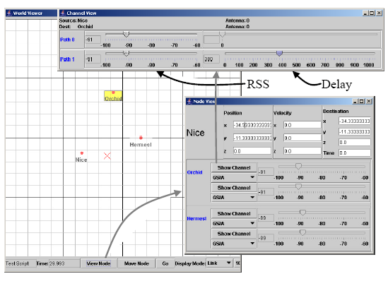 Figure 4: Emulation Controller
In script mode, the Emulation Controller
is driven by scripts that specify
each node's movement, communication, and application behavior.
As the RF nodes move about in the emulated physical space,
the Emulation Controller continuously computes attenuation
of each signal path and the scaling factors required to emulate this
attenuation (our prototype currently uses a simple large-scale path
loss model based on measurements
in our local environment).
After computation, these scaling factors are sent
to the DSP Engine.
Emulation Controller scripts can also generate
network traffic between any pair of nodes, and synchronize this traffic with
node movement and application behavior.
The Emulation Controller also generates a visual display
of node location in the emulated physical environment as
shown in Figure 4.
In interactive mode, the GUI shown in Figure 4
may be used to move nodes in the
emulated physical environment. As shown in the "Node View" and
"Channel View" windows of Figure 4,
interactive mode also allows manual control of both received signal
strength and delay for each channel.
The experiments we discuss in later sections make use of both the
scripted and the manual control modes of the Emulation Controller.
Figure 4: Emulation Controller
In script mode, the Emulation Controller
is driven by scripts that specify
each node's movement, communication, and application behavior.
As the RF nodes move about in the emulated physical space,
the Emulation Controller continuously computes attenuation
of each signal path and the scaling factors required to emulate this
attenuation (our prototype currently uses a simple large-scale path
loss model based on measurements
in our local environment).
After computation, these scaling factors are sent
to the DSP Engine.
Emulation Controller scripts can also generate
network traffic between any pair of nodes, and synchronize this traffic with
node movement and application behavior.
The Emulation Controller also generates a visual display
of node location in the emulated physical environment as
shown in Figure 4.
In interactive mode, the GUI shown in Figure 4
may be used to move nodes in the
emulated physical environment. As shown in the "Node View" and
"Channel View" windows of Figure 4,
interactive mode also allows manual control of both received signal
strength and delay for each channel.
The experiments we discuss in later sections make use of both the
scripted and the manual control modes of the Emulation Controller.
3.2 Version 2
Our prototype emulator confirmed the power of our
approach [4], and proved itself to
be an extremely useful tool in its own right.
Nevertheless, the scale, fidelity, and bandwidth
of our prototype were limited by the fact
that we used an inexpensive off-the-shelf evaluation
board for the DSP Engine. The dynamic range of our emulator
was limited by the prototype Signal Conversion Module's use of simple
connectorized components.
"Version 2" of our emulator addresses these key limitations of the prototype.
We now describe this implementation;
Section 3.3 then presents the results of experiments
that show the fidelity of Version 2.
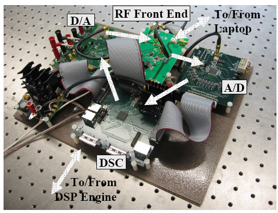 Figure 5: Production Emulator Implementation
Our Version 2 DSP Engine is currently under development. It
will have the same fundamental architecture as the
prototype DSP Engine, but it will greatly improve on the prototype
by using a much larger FPGA on a custom board with high-speed connectors
to the Signal Conversion Modules. It will be able to
support 15 RF nodes and 100 MHz of bandwidth versus
3 nodes and 25 MHz for the prototype, and will
also allow for much finer grained control of signal fading.
The Version 2 Signal Conversion Module is complete and functional.
A fully assembled Signal Conversion Module is shown
in Figure 5.
The RF Front End board on this module replaces the connectorized
components used in the prototype,
and increases the dynamic range of Version 2
to 60 dB versus 40 dB for the prototype.
(Version 2 achieves 50 dB isolation from
the strongest spurious signal caused during emulation).
The A/D and D/A boards used in this module are capable of running at
210 Msps which is over 3 times that of the prototype. This allows us to
capture around 100 MHz of bandwidth directly, and is
sufficient to capture all North American 802.11b/g
channels or a portion of 802.11a.
Unlike the prototype, the Version 2 Signal Conversion Module utilizes
a "Digital Signal Conversion" (DSC) board. The inclusion of this board arose
from the need to convert high-speed digital signals from the different
signaling requirements used by the A/D, D/A, and the DSP Engine.
For flexibility, this board was implemented using a modest FPGA,
which allows each DSC to assist the DSP Engine in certain cases.
Figure 5: Production Emulator Implementation
Our Version 2 DSP Engine is currently under development. It
will have the same fundamental architecture as the
prototype DSP Engine, but it will greatly improve on the prototype
by using a much larger FPGA on a custom board with high-speed connectors
to the Signal Conversion Modules. It will be able to
support 15 RF nodes and 100 MHz of bandwidth versus
3 nodes and 25 MHz for the prototype, and will
also allow for much finer grained control of signal fading.
The Version 2 Signal Conversion Module is complete and functional.
A fully assembled Signal Conversion Module is shown
in Figure 5.
The RF Front End board on this module replaces the connectorized
components used in the prototype,
and increases the dynamic range of Version 2
to 60 dB versus 40 dB for the prototype.
(Version 2 achieves 50 dB isolation from
the strongest spurious signal caused during emulation).
The A/D and D/A boards used in this module are capable of running at
210 Msps which is over 3 times that of the prototype. This allows us to
capture around 100 MHz of bandwidth directly, and is
sufficient to capture all North American 802.11b/g
channels or a portion of 802.11a.
Unlike the prototype, the Version 2 Signal Conversion Module utilizes
a "Digital Signal Conversion" (DSC) board. The inclusion of this board arose
from the need to convert high-speed digital signals from the different
signaling requirements used by the A/D, D/A, and the DSP Engine.
For flexibility, this board was implemented using a modest FPGA,
which allows each DSC to assist the DSP Engine in certain cases.
3.3 Validation
Experiments demonstrating the
performance of our prototype were presented in [4].
We now present experiments validating the fidelity and isolation
of Version 2 which show significant improvement
over the prototype's performance.
As the DSP Engine operates entirely on digital signals,
the fidelity of the emulator is determined by the
Signal Conversion Module. Hence, we may measure
the fidelity of our production emulator solely by
measuring the fidelity of the Signal Conversion Module.
We employed this approach by using two Signal Conversion
Modules to emulate two RF signal paths.
The FPGAs on the DSC boards implement the signal
attenuation required for these tests.
These tests used Engenius NL-2511CD Plus Ext2 wireless cards.
Fidelity.
A signal's physical layer fidelity is measured by comparing
it with an ideal signal; the signal is measured by
periodically sampling
the signal and plotting the results on a polar graph
as shown in Figure 6.
This
is known as the signal's "constellation". (In the figure,
each constellation contains four clusters of points.)
We can then
visually compare the measured constellation against an ideal
constellation.
We can quantify the difference
between a measured signal and an ideal signal by measuring
"error vector magnitude" (EVM). EVM is the relative difference
between ideal signal constellation points and observed constellation
points.
EVM measures the average magnitude of the error vector
(a vector from the ideal constellation point to the observed point)
as a percentage of the ideal signal vector's magnitude.
Figure 6 compares the modulation
fidelity of a signal generated by a digital signal generator (a) with
that of the same signal passed through our production emulator (b) and
(c). Comparing (a) with (b) we see that when the emulator is digitizing
in narrowband mode (a single 802.11b channel) the constallation loses
some crispness, but is still excellent; EVM increases slightly.
(c) shows that when digitizing a wideband signal (802.11b channels
1-11) the signal degrades slightly more, but is still quite good. The
EVM measurement in this case should not be regarded as saying that there
is no signal degradation in wideband mode, but merely shows that the
degradation is within the margin of measurement error.
Our earlier prototype work [4] demonstrated that our
emulator does not distort on-card measurements such as
received signal strength (RSSI). This previous work also showed that the
prototype link delivery performance was close to that of a coaxial-based
comparison, and that signal modeling was repeatable across experiments.
We omit similar tests from this work in the interest of space.
Figure 7 demonstrates that our prototype's
physical and link layer fidelity translates into transport level fidelity by
comparing the
TCP throughput for two laptops connected via coaxial cable and
discrete attenuators versus two laptops connected via our production emulator.
Each data point is an average of 20 trials measuring one-way TCP
throughput for approximately 5 seconds. Confidence intervals are
omitted since they are tight, and the SNR measurement error
is dominant (about 1 dB). The results match quite closely and are
within the measurement error of the experiment.
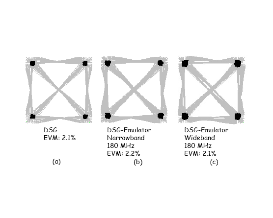 Figure 6: Physical Layer Fidelity
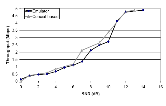 Figure 7: Transport Layer Fidelity
Isolation.
An important benefit of our prototype is the ability to conduct
experiments in isolation from external sources of interference.
To measure this, we used a high power source (20 dBm) external to our emulator with a
strong omnidirectional antenna (5.5 dBi) to send traffic at 1Mbps.
We then moved this traffic source around our immediate environment
to see when our emulator could not sense any of this traffic.
Our results showed that our emulator was isolated against this
strong source when it was at least 10 meters away. The current
limitation on this isolation is the need to sacrifice perfect
shielding in order to allow the RF nodes to be cooled.
Additional work should cut the interfering range down to a few
meters even for strong transmitters.
Building a large setup requires that we place RF nodes in close
proximity to each other. To allow for this while maintaining
internal isolation, each emulator node is mounted inside of a shielded
rack-mount chassis.
By altering the external isolation test to measure internal isolation, we
verified that nodes attached to the emulator are effectively isolated
against undesired transmission to each other despite their close proximity
(8.75 inches).
We next discuss how our emulator's ability to faithfully control the
wireless signal is used to model signal propagation. We will
then discuss several experiments that demonstrate the range
of experiments enabled by our emulator.
Figure 7: Transport Layer Fidelity
Isolation.
An important benefit of our prototype is the ability to conduct
experiments in isolation from external sources of interference.
To measure this, we used a high power source (20 dBm) external to our emulator with a
strong omnidirectional antenna (5.5 dBi) to send traffic at 1Mbps.
We then moved this traffic source around our immediate environment
to see when our emulator could not sense any of this traffic.
Our results showed that our emulator was isolated against this
strong source when it was at least 10 meters away. The current
limitation on this isolation is the need to sacrifice perfect
shielding in order to allow the RF nodes to be cooled.
Additional work should cut the interfering range down to a few
meters even for strong transmitters.
Building a large setup requires that we place RF nodes in close
proximity to each other. To allow for this while maintaining
internal isolation, each emulator node is mounted inside of a shielded
rack-mount chassis.
By altering the external isolation test to measure internal isolation, we
verified that nodes attached to the emulator are effectively isolated
against undesired transmission to each other despite their close proximity
(8.75 inches).
We next discuss how our emulator's ability to faithfully control the
wireless signal is used to model signal propagation. We will
then discuss several experiments that demonstrate the range
of experiments enabled by our emulator.
4 Signal Propagation Modeling
With our ability to completely control wireless signal propagation
comes the challenge of modeling or recreating propagation in an appropriate
manner for a given experiment. Our goal in this work is not to
develop and justify new physical models of signal propagation,
but to discuss how current and future models
as well as signal propagation trace playback can be used in
our emulator.
Fortunately, unlike wireless simulators, we are freed from the task
of emulating radio behavior in conjunction with signal propagation
modeling: we simply pick a suitable signal
propagation model, compute each receiver's received signal,
and let the radio decide what happens.
We do not need to make any assumptions regarding any radio issues such
as "sensing range"or "interfering range".
We now discuss several different methods of modeling wireless signal
propagation in our emulator. We begin with signal
propagation models that require no site specific information,
and then discuss models that use increasing amounts of site specific
information.
Some of these techniques are completely operational in our emulator
(large-scale path loss, signal capture and replay), some are
partially operational (small-scale fading), while others require
some external tools before they can be used in our emulator (ray-tracing,
channel sounding).
4.1 Large-scale Path Loss
The signal propagation model most commonly used by simulators is
a large-scale path loss model. Specifically, the received signal
strength at each receiver (RSS) is computed as RSS = Pt + Gt - PL + Gr.
Where Pt and Gt are the transmit power and antenna gain at the transmitter,
PL is the path loss, and Gr is the antenna gain at the receiver.
Large-scale path loss models simply compute PL as a function of distance
between the transmitter and the receiver.
The Emulation Controller implements large-scale path loss by simply
calculating the loss between nodes whenever the distance between them
changes. These loss values are then sent into the emulator where
they are used to control the attenuation of the signal path between
two nodes.
4.2 Small-scale Fading
While large-scale fading models can accurately capture the average
path loss between two points, on a short time scale the path loss
between these points may vary substantially. To support this
behavior, we are currently adding the ability in our emulator to
emulate this small-scale fading.
We are leveraging the technique presented in [6] to incorporate
the Ricean and Raleigh statistical models of small-scale fading
in our emulator. In our implementation, the fading parameters are computed
offline, and are then loaded into our emulator's FPGA before emulation
begins. At run time, these parameters are added to the large-scale
path loss which causes short term variation with the desired
statistical properties. Independent use of fading
parameters should allow independent, on-line modification of
small-scale fading for each RF node.
4.3 Ray Tracing
The previous two methods required no site specific information
other than picking the correct path loss models and model
parameters. By incorporating site-specific information, it
is possible to generate more accurate signal propagation
models.
One technique that can be implemented in the emulator
is to leverage ray tracing techniques. If the motion of nodes
can be pre-computed off-line, ray-tracing techniques can
be used to precisely compute all rays incident on each
receiver at a given point in time. If motion cannot
be pre-computed, then approximations can be made.
At runtime, the pre-computed series of attenuation over time
values for each signal path would then be used to set path
attenuation inside the DSP Engine.
4.4 Capturing and Replaying Signal Behavior
One simple method of accurately modeling signal propagation
is to measure the signal propagation in a given environment
and then to replay it. We have implemented a signal capture
system using standard wireless NICs that measures path loss
in a physical environment. This system works by constantly
sending small packets from each transmitter to be emulated
and receiving these packets on each receiver being emulated.
Our emulator then simply replays the observed traces
of signal strength. To demonstrate this capability, we captured
path loss from a car driving along a freeway at 60 MPH
to a base station located at a fixed point near the freeway.
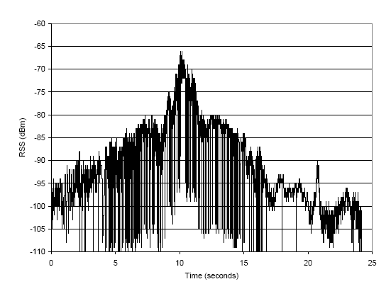 Figure 8: Freeway Driveby Measured RSS
The traffic source was a 23 dBm 802.11b source attached to a 5 dBi isotropic
antenna placed on the roof of the passing car. The receiver used the same
hardware as the sender, but with the antenna placed on the roof of a stationary
car at the side of the freeway. As the sender passed, it continuously broadcast
small 1 Mbps broadcast packets which were recorded by the receiver.
The result of this test was signal strength measurements with 1 ms granularity.
We then post-processed this trace to extract the timestamped signal and
noise measurements.
Figure 8 shows the trace extracted using this method.
Our emulator then simply reads, and recreates the observed path loss
at the given time. Our current trace replaying software is limited to 2.5 ms
granularity.
Figure 8: Freeway Driveby Measured RSS
The traffic source was a 23 dBm 802.11b source attached to a 5 dBi isotropic
antenna placed on the roof of the passing car. The receiver used the same
hardware as the sender, but with the antenna placed on the roof of a stationary
car at the side of the freeway. As the sender passed, it continuously broadcast
small 1 Mbps broadcast packets which were recorded by the receiver.
The result of this test was signal strength measurements with 1 ms granularity.
We then post-processed this trace to extract the timestamped signal and
noise measurements.
Figure 8 shows the trace extracted using this method.
Our emulator then simply reads, and recreates the observed path loss
at the given time. Our current trace replaying software is limited to 2.5 ms
granularity.
4.5 Channel Sounding
A more sophisticated method of measuring signal propagation in
a physical environment is to use specialized hardware to
precisely measure the "impulse response" of the channel. Such measurements
can be difficult to obtain since they require specialized hardware.
Once obtained, however, our emulator is capable of replaying these measurements by
setting the attenuation and delay of each signal path in the DSP Engine according to
the values extracted from the channel sounding.
4.6 Discussion
Before presenting experimental results, we briefly discuss
the capabilities and limitations of signal propagation modeling
using our approach.
Simulation.
Many of the signal propagation models that we utilize can
be also be used in simulation. This superficial similarity,
however, belies a massive difference in how these models
are used.
Computational constraints placed on a simulator, force the simulator to work
at a very coarse timescale.
Our emulator, on the other hand,
uses a statistical propagation model to manipulate a real
modulated signal on the timescale of 5 ns. This is then sent
to a real receiver to determine the reception behavior.
Accurate receiver behavior in a simulator would require transistor
level simulation which is completely infeasible for the number
of nodes that we are looking at. Realtime simulation of such
behavior is out of the question.
Similarly, while a simulator can replay a captured channel trace,
it can only do so at a very coarse timescale and with far less fidelity
than a physical layer emulator.
Real-world experimentation.
The ability to precisely recreate a signal propagation environment
is a huge advantage compared to real-world experimentation. This
power, however, comes with a price of reduced realism and scale in signal
propagation.
Our approach necessarily models a wireless channel using discrete
elements (e.g. one line-of-sight ray and two reflections) whereas
a true wireless channel is a continuous phenomenon. Also, as the number of
RF nodes attached to our DSP Engine increases, the number and
length of delayed signal paths that we can implement drops.
Hence our approach is a compromise between the fidelity of the real-world and
the control of simulation.
Noise.
The term noise is frequently used to refer to both true
noise (e.g. receiver noise) and interference from other
wireless devices. Receiver noise is naturally
present in our system since we use real receivers.
Interference from other wireless devices can be supported
in several ways. First, if RF Node ports are free and the devices
are available, these devices can simply be attached to our emulator.
Secondly, it is possible to record noise resulting from interference
and to replay this in the emulator. Third, a white noise generator
can be implemented in either the DSP Engine or the DSC card to
generate noise.
Note that our effective receiver noise floor will be slightly higher
than a coaxial based system since we use additional amplifiers
etc. that introduce noise.
This level will still be much lower than the noise floor of a
true free-space wireless system.
Scale.
As hardware is finite, the richness of channel modeling possible
using hardware-based emulation drops as the scale of the network
being emulated increases. The limiting factor is typically the
number of multipliers in the DSP Engine's FPGA.
For much of our discussion, we have
assumed the desire to support the independent pairwise emulation of
all pairs of RF Nodes attached to an emulator. Clearly this approach
becomes infeasible at a certain point as the complexity of pairwise
interaction is order n2.
It is important to observe, however that emulating complete interaction is
not always necessary. Clearly,
if nodes are out of range with respect to each other, then no
emulation between them is necessary.
In addition, complexity
may be reduced by simplifying and aggregating the emulation of
channels for distant nodes.
Multi-element Air Interface Support.
Current wireless networks are pushing the limits of the
throughput that are possible with a single element antenna.
Future networks will increase throughput by using multiple
elements to support techniques such as steerable antennas,
MIMO, and "time reversal".
Our emulator can support such emerging technologies in
two ways. First, where hardware exists, our emulator can
support these multi-element experiments by simply treating
each element as an independent RF node. The control
software then simply controls these RF nodes in a coordinated
fashion which also opens up some room for reducing FPGA
resources consumed. Second, in certain circumstances,
it may be possible for the emulator to emulate the effect of
a given technology. For instance, a steerable antenna can
be completely emulated without necessarily using a true
steerable NIC.
5 Experiments
Our emulator enables a broad set of experiments to be conducted
in a controlled and automated environment.
To give a feel for
the power of our emulator as a research tool, we now present
several experiments that illustrate various types experimentation
that our emulator enables.
We first discuss
how our emulator can improve understanding of the
impact of the physical layer on higher layers.
We then discuss our emulator's
support for emerging antenna and air interface technologies.
Finally, we discuss how our emulator can be used to conduct
micro and system level benchmarks of wireless performance.
Section 6 will then present a case study
showing how our emulator can be used to analyze a wireless protocol improvement.
These experiments were all conducted using one or more of three RF Nodes
connected to our prototype:
"Orchid", "Hermes", and an interferer ("Nice" or a
Bluetooth source). For experiments conducted in an emulated physical
environment (i.e. where manual control of channel parameters is
not required), we use a log-based path loss model derived from our
local environment.
For each of the experiments discussed, obtaining realistic results
using traditional methods would be difficult or inaccurate.
5.1 Physical Layer Impact on Higher Layer Performance
5.1.1 Hidden Terminal
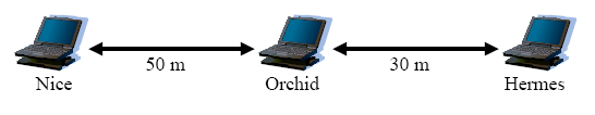 Figure 9: Hidden Terminal Topology
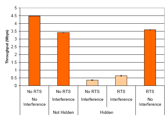 Figure 10: Hidden Terminal Results
A well known example of a low layer issue that has potentially serious
ramifications for application performance in wireless networks
is the "hidden terminal" problem.
Evaluating the hidden terminal problem in a real world environment
is troublesome since it is difficult to determine if nodes are
in carrier sensing range of each other. Moreover, carrier sensing
range constantly fluctuates in the real world.
This experiment highlights our prototype's ability to
overcome these difficulties by providing
precise, independent control over the signal paths between all nodes.
This allows us to evaluate the hidden terminal problem by simply
commanding the emulator to "disconnect" the desired nodes while
leaving the communication between other nodes unaffected.
As illustrated in Figure 9 we arranged
our three nodes in a line with all nodes in range of each other.
(For simplicity we will speak of spatial relationships in
our virtual physical environment as if they were based in a real physical
environment).
We then measured TCP throughput from Hermes to Orchid while Nice
was used to generate interfering
traffic using a unicast ping flood directed at Orchid.
Orinoco cards were used for these tests.
As shown in the Figure 10
"No RTS, No Interference" test, throughput between Orchid and Hermes
is excellent when there is no interference
(each value is an average of 25 trials with 95% confidence intervals shown).
In the "No RTS, Interference, Not Hidden" test, we see that when Nice
begins interfering, throughput is still quite good
(ping packets are much smaller than the TCP packets).
We then created a hidden terminal situation
by artificially "severing" the link between Hermes and Nice while leaving
the other communication paths unaffected. (The ability to create
a hidden terminal situation without "moving" the nodes allows us to
directly compare results between the hidden and non-hidden tests.)
The "No RTS, Interference, Hidden" test shows that throughput between
Orchid and Hermes drops dramatically in this case.
We next analyzed the efficacy of 802.11's RTS/CTS mechanism
at overcoming the hidden terminal problem by
repeating the previous tests with Hermes set to always use RTS/CTS
for frames over 200 bytes.
The "RTS, Interference, Hidden" test shows that RTS/CTS is
able to double throughput; nevertheless throughput is still much
lower than when the interferer was not hidden.
Comparing the final "RTS, No Interference" test with the
"No RTS, No Interference" case shows that the overhead of RTS/CTS alone
is roughly 1 Mbps. Further investigation (and coaxial-based verification)
revealed that the cause of this underwhelming improvement was the
failure of RTS/CTS to prevent rate fallback. The ability to analyze
this type of subtle behavior in a controlled environment is a key
advantage of our emulator.
Figure 10: Hidden Terminal Results
A well known example of a low layer issue that has potentially serious
ramifications for application performance in wireless networks
is the "hidden terminal" problem.
Evaluating the hidden terminal problem in a real world environment
is troublesome since it is difficult to determine if nodes are
in carrier sensing range of each other. Moreover, carrier sensing
range constantly fluctuates in the real world.
This experiment highlights our prototype's ability to
overcome these difficulties by providing
precise, independent control over the signal paths between all nodes.
This allows us to evaluate the hidden terminal problem by simply
commanding the emulator to "disconnect" the desired nodes while
leaving the communication between other nodes unaffected.
As illustrated in Figure 9 we arranged
our three nodes in a line with all nodes in range of each other.
(For simplicity we will speak of spatial relationships in
our virtual physical environment as if they were based in a real physical
environment).
We then measured TCP throughput from Hermes to Orchid while Nice
was used to generate interfering
traffic using a unicast ping flood directed at Orchid.
Orinoco cards were used for these tests.
As shown in the Figure 10
"No RTS, No Interference" test, throughput between Orchid and Hermes
is excellent when there is no interference
(each value is an average of 25 trials with 95% confidence intervals shown).
In the "No RTS, Interference, Not Hidden" test, we see that when Nice
begins interfering, throughput is still quite good
(ping packets are much smaller than the TCP packets).
We then created a hidden terminal situation
by artificially "severing" the link between Hermes and Nice while leaving
the other communication paths unaffected. (The ability to create
a hidden terminal situation without "moving" the nodes allows us to
directly compare results between the hidden and non-hidden tests.)
The "No RTS, Interference, Hidden" test shows that throughput between
Orchid and Hermes drops dramatically in this case.
We next analyzed the efficacy of 802.11's RTS/CTS mechanism
at overcoming the hidden terminal problem by
repeating the previous tests with Hermes set to always use RTS/CTS
for frames over 200 bytes.
The "RTS, Interference, Hidden" test shows that RTS/CTS is
able to double throughput; nevertheless throughput is still much
lower than when the interferer was not hidden.
Comparing the final "RTS, No Interference" test with the
"No RTS, No Interference" case shows that the overhead of RTS/CTS alone
is roughly 1 Mbps. Further investigation (and coaxial-based verification)
revealed that the cause of this underwhelming improvement was the
failure of RTS/CTS to prevent rate fallback. The ability to analyze
this type of subtle behavior in a controlled environment is a key
advantage of our emulator.
5.1.2 External Interference
Another well known problem that can afflict wireless networks in a
license free band is interference from external sources.
To illustrate our ability to investigate interference
from arbitrary sources we conducted a simple experiment
involving two 802.11b nodes communicating in the face of
interference from a Bluetooth source.
As shown in Figure 11,
each node was positioned 50 meters from the other two nodes.
Figure 12 shows the results of communication
between Hermes and Orchid for four scenarios (each value is an average of 25
trials with 95% confidence intervals shown), two of which - the
"Yagi" cases - will be discussed in the next section.
In the "Isotropic, No Interference"
test, Hermes and Orchid communicate with omnidirectional antennas
with no interference (using a TCP benchmark with traffic from Orchid to Hermes).
Communication is only around 1.25 Mbps due to the distance between the nodes.
In the "Isotropic, Interference" test, Hermes and Orchid
communicate as before, but the Bluetooth source is configured
to broadcast a constant 15 dBm signal with Bluetooth modulation.
TCP communication between Orchid and Hermes is not possible in this case.
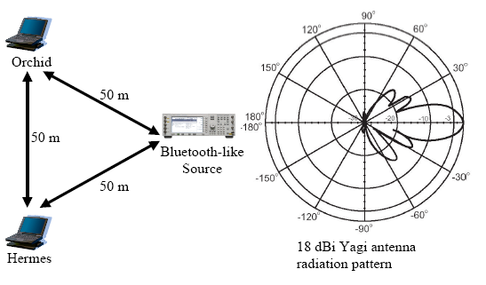 Figure 11: Directional Antenna Topology
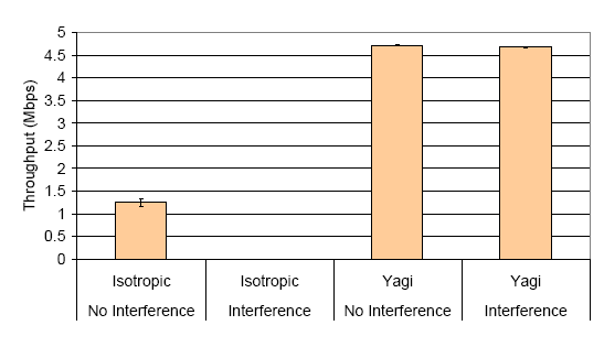 Figure 12: Directional Antenna Results
5.2 Flexible Antenna and Multi-element Air Interface Support
Complete control over signal propagation also allows our prototype
to emulate arbitrary types of antennas. To illustrate this, we
analyzed the ability of directional antennas to improve range
and spatial reuse by minimizing the effects of interfering
Bluetooth traffic (discussed in 5.1.2).
Orinoco cards were used for these tests.
The "Yagi" tests repeat the "Isotropic" tests
discussed previously,
but with 18 dBi Yagi antennas [7] attached to Orchid
and Hermes. These antennas are aimed directly at each other.
Figure 11 shows the radiation pattern for these
antennas. Note that for Orchid and Hermes, the Bluetooth source lies along a side lobe
with approximately 22 dB and 18 dB respectively less gain than the primary lobe.
As shown in Figure 12
these directional antennas successfully increase the communication rate
and also mitigate the effects of external interference.
5.3 Benchmark Experiments
We now consider "benchmark" experiments that
are designed to measure particular aspects of
wireless NIC or link behavior.
In additon to providing the control necessary for these tests,
the emulator allows these tests to be automated which greatly
reduces execution time while eliminating the error
associated with manually conducting similar experiments.
These capabilities also enabled us to compare wireless link behavior
observed in Roofnet [5] against
link behavior in a controlled emulated environment.2
5.3.1 NIC Signal Measurement Characterization
Many researchers have proposed techniques that rely
on signal strength and/or noise floor measurements
provided by the card. Two common examples are signal
strength based device location [8] and SNR based rate selection [9].
The success of these
proposed techniques hinges on the accuracy of
NIC signal measurement; very little information, however,
has been published regarding the accuracy of these
measurements in actual hardware.
To investigate the accuracy of signal measurements
made by current 802.11b cards, we tested the measurement
behavior of five wireless cards. Each card was the exact
same model: an Engenius NL-2511CD Plus Ext2 card. Using
our emulator to connect
a single transmitter-receiver pair we were able to precisely
control the received signal strength (RSS) at each card
(we held the transmitter constant while alternately measuring
each receiver).
For each signal strength between -70 dBm and -100 dBm at 2 dB intervals
we sent 500 packets of 1500 bytes each at 1 Mbps. We then
computed the average signal strength (RSSI) and noise measured by each card
(along with 95 % confidance intervals).
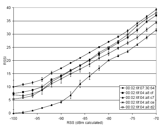 Figure 13: Per-card RSSI Variation
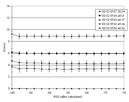 Figure 14: Per-card Noise Variation
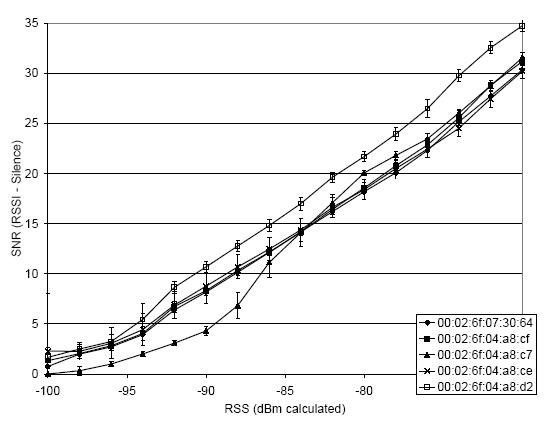 Figure 15: Per-card RSS Variation after Correction
As shown in Figure 13 there is approximately 10 dB of
variation in the measurements even for the exact same model of card.
This is clearly inadequate for many purposes.
For most cards, however, this variation seems to be caused by a constant bias.
This implies that each card's measurement behavior, RSSI, for a
given RSS can be defined as: RSSI(RSS) = RSS + Ec + E(RSS).
Where RSSI is the measured signal strength, RSS is the actual
signal strength, Ec is a constant (per-card) error term, and
E(RSS) is each card's variation of from the base Ec for a particular RSS.
Ideally, each card would have a lookup table that would give
the Ec as well as E(RSS) for each RSS. Lacking such a table,
however, we can leverage the fact that most of the error is
contained in Ec to correct RSSI.
One very simple method of obtaining a good estimate of Ec is to
min-filter the noise measurements (the filtering eliminates
spurious noise measurements).
As shown, in Figure 14, the noise measurements
over the same set of tests shows very similar variation.
That is, each card's variation in RSSI closely matches it's variation
in measured noise.
Figure 15 shows the variation in RSS
when using this technique. With the exception of one card,
this lowers the variation to approximately 4 dB. This is a
greatly reduced variation, but may not be low enough
for some purposes (e.g. signal strength based location).
Complete card characterization of the relationship between
RSSI and RSS is possible, but may not be worth the per-card
testing required.
Figure 15: Per-card RSS Variation after Correction
As shown in Figure 13 there is approximately 10 dB of
variation in the measurements even for the exact same model of card.
This is clearly inadequate for many purposes.
For most cards, however, this variation seems to be caused by a constant bias.
This implies that each card's measurement behavior, RSSI, for a
given RSS can be defined as: RSSI(RSS) = RSS + Ec + E(RSS).
Where RSSI is the measured signal strength, RSS is the actual
signal strength, Ec is a constant (per-card) error term, and
E(RSS) is each card's variation of from the base Ec for a particular RSS.
Ideally, each card would have a lookup table that would give
the Ec as well as E(RSS) for each RSS. Lacking such a table,
however, we can leverage the fact that most of the error is
contained in Ec to correct RSSI.
One very simple method of obtaining a good estimate of Ec is to
min-filter the noise measurements (the filtering eliminates
spurious noise measurements).
As shown, in Figure 14, the noise measurements
over the same set of tests shows very similar variation.
That is, each card's variation in RSSI closely matches it's variation
in measured noise.
Figure 15 shows the variation in RSS
when using this technique. With the exception of one card,
this lowers the variation to approximately 4 dB. This is a
greatly reduced variation, but may not be low enough
for some purposes (e.g. signal strength based location).
Complete card characterization of the relationship between
RSSI and RSS is possible, but may not be worth the per-card
testing required.
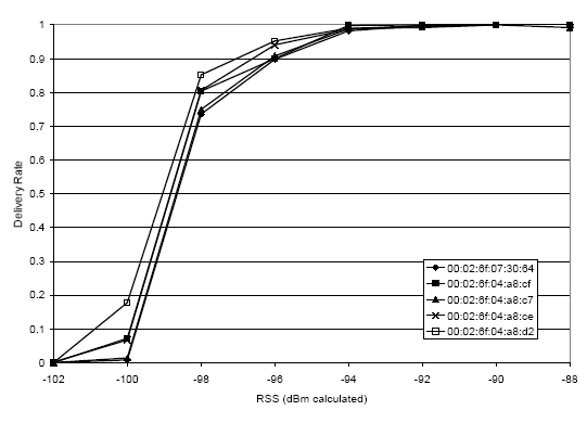 Figure 16: Per-card Delivery Rate Variation
5.3.2 NIC Delivery Rate Variation
We next measured the 1 Mbps packet delivery rates for the same five cards discussed
previously. We report delivery rate as the fraction of transmitted packets that were
received error free.
We used the same experimental setup described
in 5.3.1 with the
exception that we varied RSS between -70 dBm and -102 dBm (we omit tests
above -88 dBm as there was no loss).
As shown in Figure 16, there seems to be less
variation in delivery rates than in RSSI. Significantly, the delivery rate
performance measured roughly follows the noise measurements in
Figure 14: cards reporting lower noise levels tend to
have a higher delivery rate. Hence, some of the noise floor measurement
variation appears to be due to real variation in the noise floors of the
NICs. This is probably due to variation in the amount of noise generated
by each NIC's low noise amplifier.
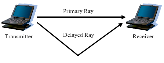 Figure 17: Two-ray Test Topology
5.3.3 Multipath Performance
We now examine card performance in the presence multipath.
To do this we configured
our emulator to emulate the signal propagation environment
shown Figure 17 using three different primary ray
strengths (-70 dBm, -90 dBm, and -95 dBm).
For each primary ray strength, we caused a delayed
ray to be emulated at all 2 dB increments of attenuation
between the primary ray strength and -100 dBm.
For each primary ray, secondary ray signal strength combination,
we varied the secondary ray's delay between 0 and 2.22 us
in 0.0185 us increments.
For each of these combinations, we conducted a test by
transmitting for 500 packets, of 1500-bytes each, from the sender.
The receiver then measured the packet delivery rate and other on-card
statistics such as signal and noise measurements (for successfully
received frames).
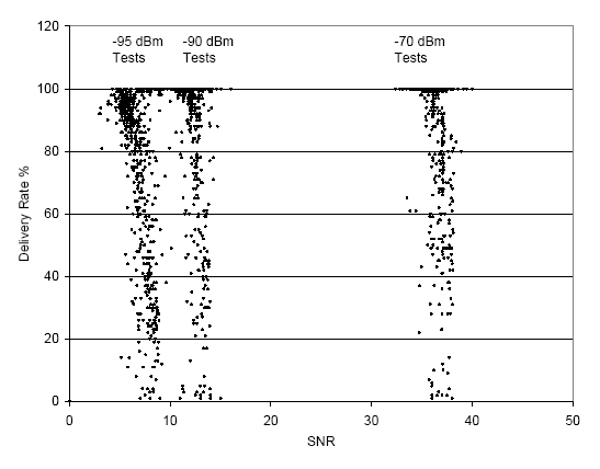 Figure 18: Two-ray Delivery Rate vs. SNR
RSSI measurements from this test (omitted in the interest of space)
showed that RSSI measured the sum of all signals incident to the receiver,
and was fairly insensitive to the delay between the signals.
The only significant exceptions being when the delayed ray
completely cancelled out the primary ray.
As seen in Figure 18, the delivery rate
exhibited large variation for different
delay spread, delayed signal strength combinations
(each point
represents a the delivery rate for one primary ray strength,
delayed ray strength, delay spread combination).
Hence, SNR may be a very poor indicator of packet delivery rate when
significant multipath is present.
We next analyzed the potential of applications to estimate
the amount of multipath present using information obtained from the
NIC's equalizer.
On the Engenius NL-2511CD Plus Ext2 cards (and all other cards based on
the same chipset), a register - "MPMetric" - is available to estimate the amount
of multipath interference present during reception.
Figure 18: Two-ray Delivery Rate vs. SNR
RSSI measurements from this test (omitted in the interest of space)
showed that RSSI measured the sum of all signals incident to the receiver,
and was fairly insensitive to the delay between the signals.
The only significant exceptions being when the delayed ray
completely cancelled out the primary ray.
As seen in Figure 18, the delivery rate
exhibited large variation for different
delay spread, delayed signal strength combinations
(each point
represents a the delivery rate for one primary ray strength,
delayed ray strength, delay spread combination).
Hence, SNR may be a very poor indicator of packet delivery rate when
significant multipath is present.
We next analyzed the potential of applications to estimate
the amount of multipath present using information obtained from the
NIC's equalizer.
On the Engenius NL-2511CD Plus Ext2 cards (and all other cards based on
the same chipset), a register - "MPMetric" - is available to estimate the amount
of multipath interference present during reception.
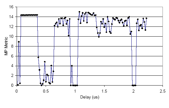 Figure 19: Two-ray MP Metric vs. Delay
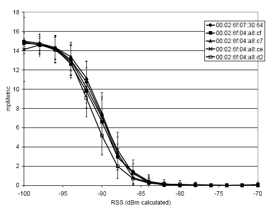 Figure 20: One-ray MP Metric vs. RSS
As the documentation on the Prism 2.5 MPMetric register is scant,
our emulator's ability to measure the behavior of this register
is critical in understanding its performance.
Figure 19
shows MPMetric as a function of delay spread for two equal-strength
rays. These measurements were
obtained from the two-ray test described earlier, and use the
five Engenius cards used previously.
From this test, we infer that if significant multipath reception is
present, MPMetric is likely to be high. We then measured MPMetric in the presence
of no multipath as shown in Figure 20. From this test we see that
the MPMetric register may also go high whenever the signal conditions are marginal
irrespective of multipath. This suggests that a high MPMetric
reading is a likely indicator of multipath when the received signal
strength is high, but it is not a useful indicator of multipath when
the received signal strength is weak.
Figure 20: One-ray MP Metric vs. RSS
As the documentation on the Prism 2.5 MPMetric register is scant,
our emulator's ability to measure the behavior of this register
is critical in understanding its performance.
Figure 19
shows MPMetric as a function of delay spread for two equal-strength
rays. These measurements were
obtained from the two-ray test described earlier, and use the
five Engenius cards used previously.
From this test, we infer that if significant multipath reception is
present, MPMetric is likely to be high. We then measured MPMetric in the presence
of no multipath as shown in Figure 20. From this test we see that
the MPMetric register may also go high whenever the signal conditions are marginal
irrespective of multipath. This suggests that a high MPMetric
reading is a likely indicator of multipath when the received signal
strength is high, but it is not a useful indicator of multipath when
the received signal strength is weak.
6 Case Study: 802.11b Rate Selection
We now present a small case study that demonstrates
how our emulator can be used to analyze and
improve wireless protocol performance.
When selecting a transmit rate, a fundamental
tradeoff that wireless protocols must make
is throughput vs. range: higher transmit rates
increase throughput but at the cost of range
and robustness to interference.
Rather than selecting a fixed
point in this tradeoff, wireless protocols such as 802.11b
support multiple transmit rates. This allows
wireless NICs to potentially select the best transmit
rate in a given environment and at a given moment.
Selecting
the best rate, however, is a difficult problem and
several schemes have been proposed. Our emulator allows
a controlled comparison of the performance of these schemes
on real hardware. For illustrative purposes we examine three
schemes: ARF - auto rate fallback, SNR signal-to-noise ratio
based scheme, and ERF - Estimated Rate Fallback. We describe each
of these approaches below.
We based our transmission rate selection implementations on the
HostAP mode Prism driver for Linux.
We made extensive alterations
in order to take fine-grained control of rate selection out of the
firmware, and put it into the driver. These alterations give us
per-packet control over transmit rate, and effectively disable
firmware rate control.
ARF Implementation.
Auto rate fallback attempts to select the best transmit
rate via in-band probing using 802.11's ACK mechanism. ARF assumes
that a failed transmission indicates a transmit rate that
is too high. A successful transmission is assumed to indicate
the current transmit rate is good, and that a higher
rate might possibly be useful.
Our ARF implementation works as follows. If a given number of
consecutive packets are sent, then increment to the next highest
transmission rate. If a given consecutive number of packets are dropped then
decrement the rate. If no traffic has been sent for a given
amount of time, then use the highest possible transmission rate
for the next transmission. In our implementation, the increment
threshold is set at 6, the decrement threshold at 3, and the
timeout value at 10 seconds. (The Prism 2.5 firmware based ARF
algorithm uses a decrement threshold of 3 and a timeout of 10
seconds, but is somewhat different than our algorithm since
retries are implemented entirely in firmware.)
SNR Implementation.
SNR based approaches attempt to eliminate the overhead of
probing for the correct transmission rate by selecting
the optimal transmission rate for a given SNR. These
schemes typically ignore multipath interference,
and assume that card RSSI/noise floor measurements are
completely characterized on a per-card basis.
SNR based rate selection algorithms are faced with the
fundamental problem that the information they need to
make the rate selection decision is measured at the receiver.
Our SNR based implementation leverages receiver
based reception information, like RBAR [9], but eliminates the
per-packet overhead and works with standard 802.11.
The key insight that our SNR based algorithm leverages is
the fact that instantaneous path loss between two given points is symmetric
in both the sending and receiving directions
3.
Hence, it's possible to estimate SNR at the receiver by
observing traffic in the reverse direction. We omit
further details of this scheme as they are beyond the
scope of this paper.
Estimated Rate Fallback.
While signal
based transmission rate selection has the benefit of quickly setting
the transmission rate, this technique may be inadequate in some
situations. Auto rate fallback, on the other hand, has the advantage
of implicitly taking all relevant channel factors into consideration,
but may probe more than necessary. We developed a simple hybrid algorithm
that uses both SNR and ARF in conjunction the on-card measurements
of multipath.
We call our scheme Estimated Rate Fallback (ERF).
The basic idea of ERF is to run the ARF and SNR based schemes
in parallel, and then to select the appropriate estimate.
We do this by using the SNR based estimate unless
one of the following is true: multipath is detected, or
the SNR estimate is near a decision threshold (2 dB in our implementation).
This allows ERF avoid the multipath weakness of the
SNR based approach while reducing the need for card characterization.
Rate Selection Algorithm Comparison
We now evaluate the performance of the previously discussed
transmission rate selection algorithms using three emulated
signal propagation environments. In all cases, we use
the same test to measure performance.
Under lightly loaded traffic conditions, optimal rate selection
is not strictly necessary since a lower transmission rate can
simply be used.
Rate selection becomes critically important, however, when the wireless
network is running at capacity.
For two of our tests,
we examine this fully loaded condition for a single transmit-receive
pair. For the third test, we examine a lightly loaded situation.
To measure performance of a single transmitter under full load, we
transmitted as many unicast UDP 1400-byte packets as possible from the
transmitting node to the receiving node under the given signal
environment. For the lightly loaded scenario, we sent 100 packets over
10 seconds and measured the number successfully received.
These tests highlight the emulator's ability to
enable controlled comparison of rate selection mechanisms with
a high degree of repeatability. For each experiment we briefly
discuss how the experiment would have fared using an alternate
approach.
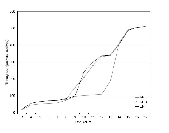 Figure 21: Rate Selection for Fixed RSS
Fixed RSS.
The first test that we conducted to evaluate our rate selection
mechanisms was to measure performance when the received
strength was constant and the source sent as much traffic as possible as
described above. Figure 21 shows our results.
As expected, SNR performs well. ARF, on the other hand, performs poorly at
intermediate signal levels where it is periodically probing for a higher
bandwidth that will never be useful. ERF, is able to match SNR performance
quite closely.
Obtaining this result using real-world experimentation would be possible, but
tedious since positioning nodes to obtain a particular fixed RSS is difficult.
Simulation might be used, but would only yield useful results if the
hardware were modeled accurately.
Figure 21: Rate Selection for Fixed RSS
Fixed RSS.
The first test that we conducted to evaluate our rate selection
mechanisms was to measure performance when the received
strength was constant and the source sent as much traffic as possible as
described above. Figure 21 shows our results.
As expected, SNR performs well. ARF, on the other hand, performs poorly at
intermediate signal levels where it is periodically probing for a higher
bandwidth that will never be useful. ERF, is able to match SNR performance
quite closely.
Obtaining this result using real-world experimentation would be possible, but
tedious since positioning nodes to obtain a particular fixed RSS is difficult.
Simulation might be used, but would only yield useful results if the
hardware were modeled accurately.
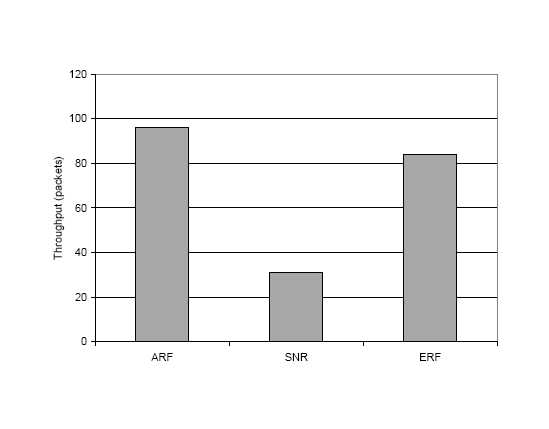 Figure 22: Rate Selection for Under Multipath
Multipath.
Next, we measured rate selection performance under in a
multipath environment by commanding the emulator to introduce
a delayed copy of the primary signal from the sender to the
receiver (ideally this would be both directions) with a fixed
delay of 1 symbol period. With the RSS of the primary ray set to -77 dBm,
we set the delayed ray strength to -84 dBm. As shown in
Figure 22, ERF and ARF perform much better than
SNR since SNR sends at 11 Mbps. This also masks the fact that SNR
uses multiple retries to even attain this throughput. This test
demonstrates that multipath can cause the SNR based scheme to fail,
although it is unclear whether this situation is common enough to
worry about in many environments. Nevertheless, ERF is able to
use hardware information to eliminate even this situation.
Eliciting this result using real-world experimentation would
essentially require a highly controlled large-scale RF test range.
Using simulation would simply not be feasible.
Figure 22: Rate Selection for Under Multipath
Multipath.
Next, we measured rate selection performance under in a
multipath environment by commanding the emulator to introduce
a delayed copy of the primary signal from the sender to the
receiver (ideally this would be both directions) with a fixed
delay of 1 symbol period. With the RSS of the primary ray set to -77 dBm,
we set the delayed ray strength to -84 dBm. As shown in
Figure 22, ERF and ARF perform much better than
SNR since SNR sends at 11 Mbps. This also masks the fact that SNR
uses multiple retries to even attain this throughput. This test
demonstrates that multipath can cause the SNR based scheme to fail,
although it is unclear whether this situation is common enough to
worry about in many environments. Nevertheless, ERF is able to
use hardware information to eliminate even this situation.
Eliciting this result using real-world experimentation would
essentially require a highly controlled large-scale RF test range.
Using simulation would simply not be feasible.
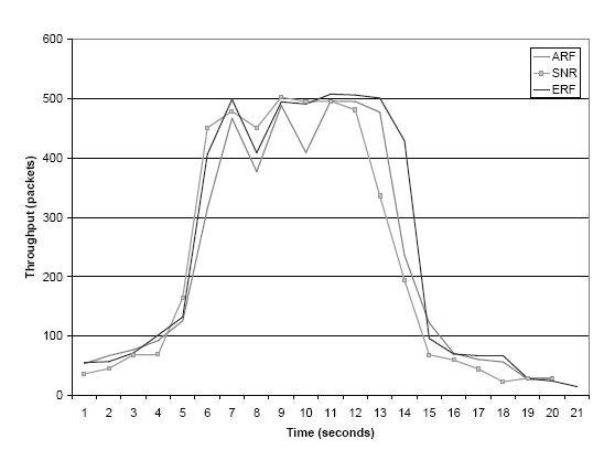 Figure 23: Rate Selection for Driveby Emulation
Fast Fading.
We next tested performance in a fast fading environment,
by measuring throughput during a replay of a "drive by"
scenario similar to that shown in Figure 8.
(In this experiment,
we are simply emulating the fast fading caused by multipath,
and are not actually emulating multiple signal copies. Hence,
the multipath differences in the various algorithms are not
demonstrated by this experiment.)
Figure 23 shows that in this
scenario, all algorithms perform similarly though
ARF and ERF generally outperform SNR when the signal is marginal,
while SNR and ERF generally outperform ARF when the signal is
strong.
This experiment demonstrates the benefits of being able
to replay the exact same signal trace. Comparing these rate
selection algorithms in a real drive-by experiment would
be difficult since even slight variations in mobility
would cause channel inconsistency across experiments.
Hence, it would be difficult to
separate the effects on performance due to the
different algorithms from the
effects due to RF channel variation.
In practice, experiments that include mobility are also
very cumbersome to execute in the real-world especially
as the number of mobile nodes increases.
A simulated test would result in a much coarser grained
use of the signal fading trace and
fail to simulate the effects of rapid fading due
to vehicle mobility. Hence, confidence in the accuracy
of such a simulated test would be greatly reduced.
Figure 23: Rate Selection for Driveby Emulation
Fast Fading.
We next tested performance in a fast fading environment,
by measuring throughput during a replay of a "drive by"
scenario similar to that shown in Figure 8.
(In this experiment,
we are simply emulating the fast fading caused by multipath,
and are not actually emulating multiple signal copies. Hence,
the multipath differences in the various algorithms are not
demonstrated by this experiment.)
Figure 23 shows that in this
scenario, all algorithms perform similarly though
ARF and ERF generally outperform SNR when the signal is marginal,
while SNR and ERF generally outperform ARF when the signal is
strong.
This experiment demonstrates the benefits of being able
to replay the exact same signal trace. Comparing these rate
selection algorithms in a real drive-by experiment would
be difficult since even slight variations in mobility
would cause channel inconsistency across experiments.
Hence, it would be difficult to
separate the effects on performance due to the
different algorithms from the
effects due to RF channel variation.
In practice, experiments that include mobility are also
very cumbersome to execute in the real-world especially
as the number of mobile nodes increases.
A simulated test would result in a much coarser grained
use of the signal fading trace and
fail to simulate the effects of rapid fading due
to vehicle mobility. Hence, confidence in the accuracy
of such a simulated test would be greatly reduced.
7 Related Work
7.1 Wireless Simulators
For several years now, ns-2 [10] has been the de facto
standard means of experimental evaluation for the wireless
networking community.
Yet ns-2's wireless support has
not kept pace with current technology, and is targeted towards the
original 802.11 standard developed in 1997.
Even this support, however, is inexact as
ns-2 does not support automatic rate selection, uses a non-standard
preamble, and a non-standard 802.11 ACK timeout value.
In addition,
ns-2's physical layer is particularly simple
[1].
As a result, some researchers are opting to use
commercial simulators such as QualNet [11] and
OpNet [12] since they claim better support for
current standards. Despite these claims, however, it is unclear
how well these simulators reflect actual hardware.
7.2 Wireless Emulators
Emulation has proven to be a useful technique in
wired networking research
[3,13,14],
and it has an even larger potential in the wireless domain.
A common approach that has been taken for wireless emulation
[15,16,17]
is to capture the behavior of a wireless network in terms of
parameters such as capacity and error rates and then use
a wired network to emulate this behavior.
This has the advantage of allowing the use of real endpoints
running real applications in real time.
The wireless MAC and physical layers, however, are only very crudely simulated.
For this reason, it is unclear
whether or not this approach can obtain more realistic results
than pure simulation.
RAMON [18]
uses three programmable attenuators to allow emulation of the signals
between a single mobile node and two base stations. While useful for the intended
application of mobile IP roaming investigation,
the inability to independently control all signal paths
severely limits this approach.
7.3 Wireless Testbeds
More recently, several efforts such as Emulab [19],
WHYNET [20], Orbit [21], and MiNT [22]
have begun using controlled wireless testbeds.
Though they mitigate some of the issues with respect to control
and isolation, these approaches still
inherit the benefits and shortcomings of testbeds discussed in Section 1.
In contrast, our approach allows for much finer grained and repeatable
control of the physical layer.
7.4 Channel Emulators / Fading Simulators
The most functionally similar approach to the wireless
emulator that we are developing is provided by commercial channel
emulators [23,24].
The goal of these emulators, however, is quite
different. Rather than supporting emulation of all channels in a wireless
network, commercial channel emulators are designed to support
very fine-grained emulation of the wireless channel between either a pair of devices
or between a small number of base stations and a small number of
mobile devices (with the total of both typically being less than 8).
In addition, these emulators lack direct support for half-duplex
nodes and require external components to support half-duplex
nodes.
As a result, while these emulators are very useful for equipment vendors
evaluating a new device,
the limited scale, lack of support for complete interaction between all
nodes, and high cost make commercial channel emulators an unattractive
option.
8 Conclusion
Understanding and improving wireless network and application
performance is increasingly important.
Unfortunately, repeatable experimentation with real
wireless nodes running real applictions operating
in a physical environment is not feasible.
For this reason, most wireless research has relied on evaluation
via simulation.
Wireless simulators do not, however, completely duplicate
real hardware in an operational environment, and the
correctness of wireless simulation is difficult to validate.
We have addressed these obstacles by developing a physically
accurate wireless emulator that supports real applications
running on real wireless devices. We have shown that this
approach allows us to achieve fine grained control over
RF propagation. We have demonstrated that this enables
the analysis of higher layer performance in real networks
and facilitates the development and evaluation of enhanced wireless protocols.
References
- [1]
-
M. Takai and J. Martin.
Effects of Wireless Physical Layer Modeling in Mobile Ad Hoc
Networks.
Proc. of MobiHOC 2001. Long Beach, CA, October 2001.
- [2]
-
L. Peterson, T. Anderson, D. Culler, and T. Roscoe.
A blueprint for introducing disruptive technology into the internet.
Proc. of HotNets-I, October 2002.
- [3]
-
B. White, J. Lepreau, L. Stoller, R. Ricci, S. Guruprasad, M. Newbold,
M. Hibler, C. Barb, and A. Joglekar.
An integrated experimental environment for distributed systems and
networks.
Proc. of OSDI 2002, December 2002.
- [4]
-
G. Judd and P. Steenkiste.
Repeatable and Realistic Wireless Experimentation through Physical
Emulation.
Proc. of HotNets-II. Cambridge, MA, November 2003.
- [5]
-
D. Aguayo, J. Bicket, S. Biswas, G. Judd, and R. Morris.
Link-level Measurements from an 802.11b Mesh Network.
Proc. of SIGCOMM 2004. Portland, OR, August 2004.
- [6]
-
R. Punnoose, P. Nikitin, J. Broch, and D. Stancil.
"optimizing wireless network protocols using real-time predictive
propagation modeling".
Proc. of the Radio and Wireless Conference (RAWCON) 1999,
August 1999.
- [7]
-
SmartAnt Telecomm Ltd.
Yagi antennas,
https://www.smartant.com/Products/ISM/2.4G/FYW24-01518BFL.pdf.
- [8]
-
P. Bahl, V. N. Padmanabhan, and A. Balachandran.
A software system for locating mobile users: Design, evaluation, and
lessons.
Tech. Rep. MSR-TR-2000-12, Microsoft Corporation, February 2000.
- [9]
-
G. Holland, N. Vaidya, and P. Bahl.
A Rate-Adaptive MAC Protocol for Multi-hop Wireless Networks.
Proceedings of MobiCom2001. Rome, Italy, September 2001.
- [10]
-
S. McCanne and S. Floyd.
UCB/LBNL/VINT Network Simulator - ns (version 2), April 1999,
https://www.isi.edu/nsnam/ns/.
- [11]
-
Scalable Network Tech.
Qualnet, https://www.scalable-networks.com/.
- [12]
-
OPNET Tech.
Opnet, https://www.opnet.com.
- [13]
-
K. Fall.
Network emulation in the vint/ns simulator.
Proc. of The Fourth IEEE Symposium on Computers and
Communications, July 1999.
- [14]
-
A. Vahdat, K. Yocum, K. Walsh, P. Mahadevan, D. Kostic, J. Chase, and
D. Becker.
"scalability and accuracy in a large-scale network emulator".
Proc. of OSDI 2002, Dec. 2002.
- [15]
-
B. Noble, M. Satyanarayanan, G. Nguyen, and R. Katz.
Trace-based mobile network emulation.
Proc. of SIGCOMM 1997, September 1997.
- [16]
-
P. Mahadevan, K. Yocum, and A. Vahdat.
Emulating large-scale wireless networks using modelnet.
Poster and Abstract Mobicom 2002, September 2002.
- [17]
-
T. Lin, S. Midkiff, and J. Park.
A dynamic topology switch for the emulation of wireless mobile ad hoc
networks.
Proc. of the 27th Annual IEEE Conference on Local Computer
Networks (LCN'02), November 2002.
- [18]
-
E. Hernandez and S. Helal.
"ramon: Rapid mobility network emulator".
Proc. of the 27th IEEE Conference on Local Computer Networks
(LCN'02), November 2002.
- [19]
-
B. White, J. Lepreau, and S. Guruprasad.
Lowering the barrier to wireless and mobile experimentation.
Proc. of HotNets-I, October 2002.
- [20]
-
WHYNET.
Whynet, https://chenyen.cs.ucla.edu/projects/whynet/.
- [21]
-
D. Raychaudhuri, I. Seskar, M. Ott, S. Ganu, K. Ramachandran, H. Kremo,
R. Siracusa, H. Liu, and M. Singh.
Overview of the ORBIT Radio Grid Testbed for Evaluation of
Next-Generation Wireless Network Protocols.
Proc. of WCNC 2005. New Orleans, LA, March 2005.
- [22]
-
S. S. P. De, A. Raniwala and T. Chiueh.
MiNT: A Miniatuirized Network Testbed for Mobile Wireless Research.
Proc. of Infocom 2005. Miami, FL, March 2005.
- [23]
-
PROPSim.
Propsim c8 wideband multichannel simulator,
https://www.propsim.net/.
- [24]
-
Spirent Communications.
Tas4500 flex5 rf channel emulator,
https://www.spirent-communications.com/.
Footnotes:
1This research was funded in part by the NSF under award
numbers CCR-0205266 and CNS-0434824. Additional support
was also provided by Intel.
Glenn Judd is supported by an Intel Fellowship.
2This was done
in conjunction with the Roofnet project
3We assume a
single receive and transmit antenna. Our approach can be
modified to support the general case.
File translated from
TEX
by
TTH,
version 3.67.
On 29 Mar 2005, 10:16.
|
