
| Pp. 43-58 of the Proceedings |  |
This paper describes the author's efforts in designing an external, out-of-band hardware monitoring and control system for use with microcomputer-based server, storage and communications systems deployed in a data center environment. This system, when complete, will consist of a collection of microcontroller-based monitoring nodes, one per monitored device. Each of these intelligent monitoring nodes will be able to keep track of several temperatures, power supply voltages, fan speeds, and various indicators of system activity. In addition, they will have the ability to control a monitored system under the direction of an administrator sitting at a web browser. As of this writing, much of the initial research and architectural planning is complete. One prototype board has been built and shown to function as expected, and most of the required development tools and licenses have been procured. The hardware design for the first pilot/production board is largely complete. It is expected that these first boards will be built and assembled by late 2000, and software development for this project will extend into 2001.
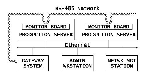
The Automation and Research Computing Section (ARC), part of the Division of Research and Statistics (R&S) at the Federal Reserve Board (FRB), runs a reasonably extensive computer network for the staffs of R&S and of the Division of Monetary Affairs (MA). There are a total of about three hundred fifty persons in the user community. This ``R&S/MA Research Computing Network'' consists of more than five hundred computers and over one hundred other network addressable devices - switches, routers, printers, etc.
This network was installed in 1987, and consisted then primarily of Sun 3 servers which were scattered throughout the office areas in the supported divisions. Most users had VT220-type terminals on their desks, while a few researchers had their own Sun workstations. Over time, most desktop devices were upgraded to X terminals, but the servers - which were regularly upgraded and steadily increased in number - remained located in the end-users' office space.
In 1997, the Board's central IT division replaced an aging mainframe and disk farm with newer models which took up a miniscule amount of space compared to the previous system. The then-barren raised-floor space was made available to ``client divisions'' as a place to put all the servers that were scattered hither and yon. R&S obtained space and resources sufficient to support thirty-five nineteen inch machine racks.
In response to this and other challenges, a complete re-design and and re-implementation of the research network was begun, a project which included the migration of all servers to the newly acquired data center space. This plan was carried out over a two-year period and was completed in mid-1999.
With this change, however, some of the remote diagnostic and control capability inherent in the previous design had been lost. Many times the telephone had been a very effective system monitoring tool - users, strategically placed near servers, were often very effective in providing notification of problems such as noisily failing fans and disk drives, even without much in the way of training. Also, if a system was so sick that it would not respond to the network, these users were often able to reset that system on request. This was especially useful on weekends when support staff were answering calls from home. The data center, however, being a secure ``glass house'' environment, was off limits to the users and thus this was no longer an option.
The new environment also resulted in some new types of problems. For example, we learned that, while one can equip a storage system with redundant power supplies, this is of limited use if there are no automatic mechanisms in place to provide notification of a failure of one of the supplies. We also learned that the white noise in a data center, together with glass rack doors, can do a remarkably good job of masking even the piercing sound of a piezo-electric alarm two rows away. Finally, the ability to monitor AC power was lost when a new building engineer declared standalone UPSs a fire hazard - the Fire Department needed a way to shut down the entire data center with a single switch, and the distributed UPSs made this problematic. A large, data center-wide UPS was installed in the sub-basement, but the ability to monitor individual circuit loads and power conditions was lost.
It became apparent that something needed to be done in order to gain better status information.
To recover our lost capabilities, we determined that a network-accessible instrumentation (or hardware monitoring and control) system was needed. While it is tempting to try to build a single system that addresses every problem, there are many advantages to breaking the problem up into a number of smaller bits that could be addressed individually.
On this basis, we saw three areas which would have high immediate impact, were reasonably inexpensive and easy or at least straightforward to do, and which addressed areas which resulted in severe support difficulties. These three areas were serial console access, power control and graphical console access.
Several of the devices installed in these racks had serial consoles to which it was fairly straightforward to provide remote access; the large number of serial ports, however, posed difficulties.
All of the production Sun servers, about 60 in total, are built from Sun Microelectronics motherboards - either the quad-processor UltraAXmp or the uniprocessor UltraAXi. One particular issue with regard to Sun SPARC machines and their serial console is that, by default, these systems will halt when an RS-232 break signal is detected.
As most people who work with Suns know, when one connects a serial console cable to the Sun, the resulting noise on the port often will generate a break condition. While the Sun's halt-on-break behavior can be disabled in the Open Boot PROM, this comes at the cost of not being able to halt a system when required. By contrast, our goal was to be able to connect and disconnect terminals at will and still maintain the ability to halt the system from the console. To solve this problem, a special ``non-aborting'' console cable from NuData - now part of MicroWarehouse [44] - was installed on each Sun server. [Note 1]
All of the RAID subsystems are again integrated in-house. We have approximately fifty RAID boxes in production, split between the SPARC and NT servers. The controller used in these subsystems is the CMD [14] CRD-5440. All configuration of this controller is done via a serial console connection on the back of the unit; the host knows not that it has a RAID controller attached.
The first implementation of a system to connect to these serial ports, over one hundred of them, was based purely on 25-pair, Cat 3 Telco trunk cables and USOC patch panels. A patch panel was installed in every rack or two, and conventional, straight-through 10-base-T patch cables were used to connect from those to custom-made serial null modem adapters [23]. The other ends of the trunk cables were brought into USOC patch panels. A few standard VT220-type terminals were installed on rack shelves; these could then be plugged into any port in those panels, switchboard operator style.
The switchboard system worked quite well, but the ultimate goal was to be able to connect to any of these ports remotely. To accomplish this, an X86 Linux server was built and outfitted with Cyclades [18] multi-port serial cards. Shell scripts driving C-Kermit [16] were written to provide command-line-based access to the piles of serial ports provided by the Cyclades cards. In this way an administrator on the Linux serial port server could simply connect to the correct console without knowing which serial device it was on. This system could be used either at the Linux system's console or through a secure network connection from anywhere in the world. The multiuser capability of the Linux box made it possible for several administrators to be working on separate systems at the same time.
This of course represents something of a single point of failure in the support infrastructure for these machines; the backup system remains the old switchboard technique, since the Linux/Cyclades system uses the same patch panels.
Each of the thirty-five machine racks was outfitted with a dedicated, 20A 120VAC circuit. To help manage these, Model 3302F intelligent power controllers from Pulizzi [56] were installed in each rack. These devices each have eight programmable power outlets, which can individually be turned off or on and can be programmed to turn on in a specific sequence with programmable time delays. These controllers can be daisy-chained on an RS-485 serial network, which then can be connected to a standard ASCII terminal or terminal emulator.
This serial network was connected to the Linux-based serial port server described in the previous section, and scripts were written to interface to that serial network and generate the correct commands to, for example, power cycle a specific port.
Windows NT, by default, does not support management through a serial console in the same way as do all these other devices. At present, we have about twenty-two Windows NT servers in production, but no room to put twenty-two monitors. To consolidate access to these devices, a cascaded-KVM switch solution from Cybex [17] was procured.
The primary disadvantage of this solution was that, much as was the case with the switchboard system for the serial consoles, it still required that that someone go to the data center to use it. A significant enhancement to this system, based on the ``VDE/200'' device from Lightwave Communications [35], is currently under evaluation. The expectation is that we will be able to use this device to deliver KVM signals to the desktops of the systems administration staff; as of this writing, we have a single, working control console on the same floor as our offices, across the street from the data center.
Still, the high bandwidth requirements of a graphical console reduce the chances of getting access to the NT server consoles from outside of the two-building local campus. One possible alternative is to provide some sort of serial console access to an NT machine. Pieces of such a solution seem to exist (see e.g. [26] ) but it is unclear at this point whether this can be made to work with NT in any satisfactory manner.
Of course, most (but not all) of these devices have some ability to be monitored via software, usually within the context of the operating system running on the device. Both Solaris and Windows NT have SNMP interfaces and a great deal can be done with advanced network and system management systems. In addition, Solaris provides a fair amount of event data through syslog, as does Windows NT through the event log.
Many of the monitoring tasks described in the latter portions of this paper could in theory be accomplished through software-based monitoring on many of these systems. For example, Sun's Advanced System Monitoring [63] package provides driver-level access to arbitrary I2C-based [55] monitoring devices, including the various monitoring probes that are provided on the system board itself. It should be a straightforward effort to map these into an extended SNMP MIB and accessed through the UC Davis SNMP daemon [65] that is used on our Solaris machines, or also possibly through CGI scripts run by Apache. [Note 2] Additionally, many newer X86 server systems support the new Intel Corporation Advanced Configuration and Power Management Interface [29]. ACPI - follow-on to the Advanced Power Management Interface (APM) - seems likely to enable the collection of a wide variety of system information.
Still, there are three essential difficulties with these software-based approaches:
Still, it was apparent that, even if all these ``easy'' tasks were completed, there would remain gaps in the available monitoring and control capabilities, and that closing those gaps was going to be substantially harder.
It seemed clear that a monitoring and control system would be more useful if it was external to the devices being monitored - in other words, if the system was designed to function out-of-band. Malfunctioning computer and networking equipment cannot be counted on to be functional enough to respond to management queries and requests. This observation was realized by problems we experienced in our early attempts to manage the Windows NT servers: it seemed that one of the first stages in almost any failure mode was to stop talking to the network.
The in-band nature of all the approaches in the previous section (with the exception of the power controllers) is a major limitation. For example, most ATX motherboards by default will only enter standby mode when powered up. This is by design and, even though this behavior can be changed in the system BIOS, there are very good reasons for the default setting - one cannot assume that the power will be stable immediately after it is first restored. Thus, even though the power controllers can reset the power to an NT server, this is only the first step in restoring the server to full function - someone must still push the ``on'' button.
While many modern computing and communications devices incorporate some monitoring and control capabilities, the implementation of these tend to be highly variable from system to system; monitoring and control procedures and software must be developed separately for each type of system. If one were to deploy, for example, a homogeneous network consisting of nothing but Sun UltraEnterprise or Compaq ProLiant servers, one could probably design a fairly successful monitoring system that depended on the specific capabilities of those devices.
However, in our research network, such an approach was not an option. As we started this wholesale network redesign, we had made a commitment to acquire most of our computer systems, including both SPARC/Solaris and X86/Windows NT servers, by integrating OEM parts in our own facility. While high-end systems such as those from Sun and Compaq are potentially more reliable, they are substantially more expensive than those which we build in-house - twice as expensive in many cases. Our assessment of this trade-off was that, without substantial budget increases, the ``more manageable'' systems could not be deployed in sufficient quantities to meet the computing demand. As a result, our production systems do not generally come with some of the advanced software tools and on-board diagnostics that might come with top-of-the-line, commercially integrated systems.
The data that may be collected from the various systems, besides being variable from system to system, is often inadequate for many purposes. For example, the Sun UltraAXmp motherboards are able to provide a threshold warning when the temperature reaches a certain level (recorded by Solaris in syslog). If the system gets much warmer, it will shut down. While this is useful, it would be more useful if it were possible to obtain a steady reading of system temperature, that could be routinely recorded into a database for trend analysis.
Also, most systems limit monitoring to what is happening inside the system itself, while it is frequently the case that one would be just as interested in what is going on outside the system. For example, rack ambient temperature and airflow can be very useful in identifying patterns in system problems. Many systems can report information concerning power supply status, but this is usually limited to the DC side of the supply; it is rare that a system will provide information concerning the AC side of the supply: current and voltage, circuit loading, power sags and spikes, etc. Many of our most difficult-to-solve problems occur as a result of failures or deficiencies in systems, such as the AC power supply, which are controlled by other parts of our organization. Obtaining good data on those can often be essential to a resolution.
Finally, much of the instrumentation - both for monitoring and control - provided out of the box with typical computer systems is designed to be useful only to an operator physically present at the system. This is, for example, the case with the power and reset buttons, as well as the indicator LEDs on the system front panel. It is rare that the system manufacturer will provide any straightforward mechanism for remote access to this native instrumentation.
Thus, in parallel with the efforts described in the previous section, an investigation was begun into the feasibility of creating a monitoring and control system which operates separately from the computer systems themselves.
In approaching this problem, several design criteria were identified:
As the whole point of this project is monitoring and control, it is well to take a look at what it is expected that the system will monitor and control, and why.
With these goals and criteria in mind, several candidate technologies were examined. But first, let us note what is not available.
The market, as far as could be determined, was barren of products that directly met the goals and criteria listed above. Generally, the industry seemed to be taking the view that computers could monitor themselves just fine. Several computer system vendors had system and network management solutions. But, almost without fail, these solutions depended on the existence of a homogeneous collection of reasonably high-end systems, and/or they functioned in-band with the operating system and primary data network. Although many vendors were consulted, and many had suggestions as to how to approach the task, not one claimed to have a solution on the shelf.
Following is an outline of several technologies which were considered for this project.
PC-104 is a standard form factor for X86 PC/AT computers, using 4'' square boards and stacking pin-and-socket connectors to carry the ISA bus. A wide variety of peripheral and I/O boards are available.
The advantage of PC-104 is the use of a standard, familiar PC architecture.
High cost. A fully-functional system can cost in excess of $1000. Proprietary aspects often complicate software development. Generic sensor interfaces require external signal conditioning circuitry.
Ampro [5], Advantech [2], Technoland.
Small boards configured with standard microcontrollers. Usually provide a variety of digital and analog interfaces, not normally designed for expansion.
Moderate cost, well-documented and less proprietary.
Limited mix of sensor interfaces often restrictive. Generic sensor interfaces require external signal conditioning circuitry.
EMAC, Inc. [36], Z-World [71], R.L.C. Enterprises [58].
Programmable Logic Controllers are programmed with basic state machine logic. Networks of individual sensors and controls are connected back to the PLC.
Very flexible; wide variety of controllers and sensors available.
PLC architecture is very limiting. individual sensors and controls are large and relatively expensive.
Advantech [2], Omega Engineering [53].
For better or worse, this is the one approach that seemed to be capable of addressing the bulk of the stated goals and criteria. Among the more popular microcontrollers, PIC microcontrollers from Microchip Technology [41] are tremendously easy to work with, and these were selected for the first attempts at custom design.
The PIC microcontrollers are programmable in their own quirky assembler language or in any of several higher-level languages, most notably C. Programs are written into the PICs with low-cost device programmers. The model which saw the most use in this project was the PIC16C76 [42], a 20MHz, 28-pin device with five analog inputs, 8KB of program memory, three timers and a real programmable serial port. These chips cost between $5 and $10 depending on quantity, and the minimal parts one needs to add to have a functional controller system (e.g. crystal, voltage regulator, a few capacitors) cost maybe another $10. On a board based on a PIC controller, one can easily include all the I/O interface circuitry that one would have needed to design for all the other solutions anyway. Several companies, e.g. MicroEngineering Labs [43] sell prototyping boards for the PIC for $10 or so - with these one can have a functional controller board with a couple of hours of soldering.
This custom design solution, although perhaps not the the one which intuition would select, proved to be by far the most straightforwardly malleable, to be the most cost effective - even when the cost of development tools is accounted for - and the most free of proprietary encumbrances. With this approach, promising, concrete results were obtained in a very reasonable timeframe.
Three technologies were considered as a choice for the physical layer: RS-485, Ethernet, and CAN. This in fact turned out to be a fairly straightforward choice, however.
RS-485, which is also basis for differential SCSI and many short-haul modems, is very simple in design. It transmits a differential signal over common copper twisted pair wire, one pair for half-duplex and two pairs for full-duplex. A ground return wire is usually present as well, so an RS-485 network cable will most likely have either three or five conductors. Data can be transmitted over such cables at relatively high rates, over reasonable distances, and with a great deal of noise immunity. RS-485 is usable in a bus topology, allowing the connection of dozens of devices to a single length of three- or five-wire cable. At distances likely to be experienced in a data center, RS-485 can easily approach speeds of 115.2 Kbps, while over short distances - as found in SCSI busses - it can support speeds as high as 10Mbps or more.
While the selection of a physical layer was fairly straightforward, there were no obvious choices for the higher-level protocol. TCP/IP was out of the question - the software required to implement TCP/IP was much too complex to deal with in an 8-bit microcontroller. There appeared to be no ``standard'' protocol available; there were several proprietary protocols such as Echelon's LonWorks [24], but it was also very common for embedded systems developers to ``roll their own'' protocol. After an evaluation of the available options, the latter approach seemed the most promising.
The outlines of an architecture for the networking of the monitoring boards was developed, although never used for reasons which will become clear. For the benefit of those who may wish to take this less proprietary approach, this architecture is described here.
In order to reduce the complexity of the code which must run on the microcontrollers, and to eliminate the need to handle collisions, we decided that the microcontrollers would speak only when spoken to. Each RS-485 string would have a single master node which would direct the microcontrollers to return data or carry out a control task. In idle time between requests, the controller would constantly be taking measurements in order to reduce the polling latency.
Each microcontroller would run a relatively simple Real-Time Operating System, which would handle task scheduling, interrupt, timer and queue management, as well as resource (e.g. memory) allocation. As requests come in off the network, a process running under the RTOS would scan request headers and select out only traffic for that controller. As each such packet comes in, a command token in the packet and any needed data would be parsed out and inserted in an appropriate job queue. A process running under the RTOS, until this point blocked in wait for the queue to fill, would be woken up and given an opportunity to act on the command.
Commands would be classed as synchronous or asynchronous. In the case of a synchronous command, the master node would do nothing - and the network would be quiet - until the slave node returned the results; a timeout would be set so that a dead node would not hang the network. In the case of an asynchronous command, the master node would wait for a receipt acknowledgement but would then go on with other work, giving the slave node time to finish the command. When the command was complete, the slave node would buffer the results and wait for another poll from the master node before attempting to return the results. A request to transmit previously requested results would of course be a synchronous command, requiring immediate response (or negative acknowledgement) If the results are never requested, the slave node would discard the results when the buffer was needed again.
Request packets would contain a preamble, a one-byte target address, a one-byte command token, one-byte request sequence number, an optional data field, a checksum and a trailer. With a single master node, a source address would not be required in a request packet. Response packets would have a slightly different preamble, the source address and response code, followed again by the sequence number, optional data, checksum and trailer. Request packets would need to be acknowledged by the microcontroller within a set time window, but response packets would not require acknowledgement; instead, the master node would simply repeat the request if required.
Start-up node discovery would be done by a simple search through all possible addresses - basic RS-485 networks support only 32 devices and this discovery can be completed in only a few seconds. [Note 4]
It is expected that the master node would be a Unix-type machine, probably Linux or BSD. On this master node, the protocol would be implemented as user-space executables which could be called by CGI scripts from the Apache web server. The service requests and results could be delivered from and to the user via the http protocol. Automatic cron jobs could run on the master node to make routine, periodic requests for data that would then be stored in a database.
There are some disadvantages of this system; it does not, for example, provide a mechanism for the microcontroller to report alerts or interrupts back to the master node. A non-responsive or ill-behaved slave node would need to be flagged as a potential problem, and an alert generated through the network management system. Also, the number of devices hanging off each serial port would also be limited by how many could successfully be polled without using up all the available bandwidth with overhead processing.
This architecture was not implemented, however, because a source, emWare [25], was identified for a product that did essentially the same thing. emWare's product, EMIT (Embedded Micro Internetworking Technology), provides a networking protocol, an http gateway, skeleton source code for several microcontrollers, and Java Beans that can be used to create a graphical interface to the networked controllers. It was estimated that that this product would take at least six to twelve months off the time to develop the instrumentation software, and a much more functional end product would result than would have otherwise.
Ultimately a wire-wrapped, PIC-based prototype was designed and built. This prototype did most of what was required, including running the EMIT software and talking to a web browser via the Java Beans. The browser window would display the constantly-updated board temperature, display counts of the HDD activity lights, and a Java-based button could be depressed to initiate a hardware reset on a Windows NT server. Finally, an affordable and buildable solution was in sight. This was in the fall of 1999, and this board was the one that was described to some LISA participants in a Work In Progress session last year.
After completing this prototype, however, it became clear that the PIC had a severe shortcoming: The PIC simply did not have enough data memory, and it had no external memory interface. The most serious problem resulting from this was in interfacing with the CMD RAID controller's serial port. Although the RAID controller had a mode for talking to such automated devices, use of that mode entailed the ability to buffer records that were comparable in size to the PIC's entire memory. Thus, a different microcontroller was going to be needed.
After a review of the alternatives, Atmel's [8] AVR architecture was selected, specifically the ATmega103. The AVR was still an 8-bit microcontroller and was still inexpensive, but the instruction set was much more powerful than the PIC's and it had an external memory interface. Over the next few months, a fairly complete board was designed around on this part, while many design details were tested on low-cost development boards that are available from Atmel. At around the end of Spring of this year, the design was nearly complete, and attention was given to the task of procuring the parts that would be required. Especially in a small project such as this, it is generally a good idea to have the parts in hand before the boards are made, so that adjustments can be made in the event that some parts are not available.
One does not normally, however, expect the availability problem to be as severe as was experienced in this case. Parts were so hard to come by this past Summer, that it was headline news every week in publications such as EE Times and Electronic Buyer's News (EBN). Pretty much anything in a surface-mount package, anything with memory in it, or anything that was used with anything that was surface mount and/or used memory - especially flash memory, was simply not available. EBN ran a story about an OEM CEO who raided his employees' Palm organizers just to get the flash memory [52] ; see also [69] and [68]. In the case at hand, about half the parts on the board - which was designed using surface-mount technology - were unavailable, most notably the Atmel microcontroller itself. Atmel reportedly was so far behind that they had ceased taking orders, and Atmel distributors were quoting lead times as long as ten months. There was no way around it, it was either shelve the whole thing for a while or go back to the drawing board.
Thus, the search began for yet another microcontroller. This time, the search was limited to devices which could (a) use as much of the existing hardware design as possible, (b) were available for immediate purchase and (c) for which there existed a port of the emWare code. Given the scarcity of parts, this turned out to be a pretty short list; very few microcontrollers of any sort were obtainable at that point. In the end, a supply of Dallas Semiconductor DS80C320 chips was located. The DS80C320 is sort of a souped-up, high-speed 8051-architecture microcontroller with no internal program storage. They also have relatively little in the way of of built-in peripherals, so the search had to be expanded to include several new parts, such as an external analog-to-digital converter and EEPROM memory. Parts in hand, work was begun to design the board one more time. However, this time around, it was going to have to be larger - the perimeter of a CD-ROM drive rather than of a floppy drive as originally planned - and would have a higher power consumption than desired. But something had to give, and at least work was still progressing.
Almost all of the parts used in this board will be ``through-hole'' as opposed to ``surface-mount''. The board itself will be designed in four layers (two signal layers, a ground layer and a power layer), with the outside dimensions about the same as that of a CD-ROM drive. Mounting holes will be drilled near the edge in such a way as to make it straightforward to mount the board, using angle brackets, in a standard 5 1/4'' drive bay. The plan is to mount this device in a free hard drive bay inside the server device. The instrumentation network and power supply for the board will enter the system through one of the I/O slot hanger brackets, and bundles of sensor wires will be connected from various locations within the server to connectors on the back of the monitor board.
A conceptual drawing of the board design is provided in Figure 2.
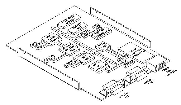
The boards are designed to operate from a +24V power supply. The relatively high DC voltage is used for two reasons: First, some devices, such as the 4-20mA current loop, need the 24V to operate. Second, the plan is to daisy-chain the power supply alongside the RS-485 network. If the boards were designed to run from a +5V power supply (voltages will need to be converted on-board in any event), the supply current would have to be higher; this would have a number of implications, including the use of heavier wires in the daisy-chain harness. The 24V power is converted to +5V, -12V and +12V on-board using off-the-shelf DC-to-DC converters.
All the run-time I/O connectors will be on one of the short edges of the board. The design calls for three connectors. One rectangular nylon connector will carry connections for power input, the RS-485 network and the 4-20mA current loop.
The other two connectors are both 26-pin high-density D-sub connectors. One will carry most of the analog connections, while the other will have the serial ports, relays, counters and other digital connections.
There will also be small header connectors on the surface of the board for the attachment of JTAG cables, for the programming of the two programmable logic parts used in the design.
In this design, there are about twenty or so integrated circuits, and about two or three dozen other parts. Some of the more interesting parts are described here; refer to Figure 3 to see how these parts work together.
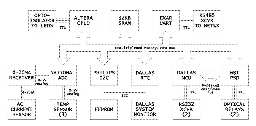
The Dallas Semiconductor DS80C320 [21] is a clone of the Intel 80C32 [30]. Dallas' part uses a new core design, runs faster than the old Intel part (up to 33MHz), and does more in each clock cycle than the traditional 8051 designs. The Dallas part also has an extra serial port, extra timers and a few extra external interrupt pins. This is actually about as nice as 8051-architecture chips get.
Waferscale [67] makes a line of highly-integrated parts that they call ``Programmable System Devices'', or ``PSDs''; the current design uses the PSD913F2 [66], which provides 160KB of flash memory in twelve sectors, 2KB of SRAM and a 57-input/19-output simple PLD. The PSD provides all the program storage for the board, some of the data storage, and handles all the address decode work needed to generate chip selects for the other ICs on the board.
National calls the LM12458 [48] a ``data acquisition system''. It is a highly programmable analog-to-digital converter, with eight inputs. The conversion circuitry can give a result with twelve bits of precision, and it can buffer several results to take some processing load off the microcontroller. It can also be programmed with threshold values, which allows for the generation of an interrupt if a sensor drifts out of specification.
The Altera MAX7064S [4] is a 64-macrocell CPLD, (Complex Programmable Logic Device). The purpose of this part here is to handle the counting of the three HDD activity LED interfaces. The three LED headers on the monitored system's motherboard will be connected (via optoisolators and buffers) to input pins on the CPLD. The CPLD increments an internal counter every time one of the counter input pins transitions from low to high. It communicates to the microcontroller though a parallel interface; the microcontroller thinks that the CPLD is just three bytes of memory.
The Dallas DS1780 [20] is a system monitor chip, designed for use on PC motherboards. It is capable of monitoring the surface temperature at the chip itself, as well as two fan speeds, several power supply voltages, and various other parameters. It has a register that latches the state of five external pins on power-up; this is designed to read an identifier off a Pentium processor, but here it is used with a DIP switch to latch the board's address on the RS-485 network. Finally, the DS1780 has a system reset circuit, which will keep all the chips on the board in a reset state until the power supply has stabilized.
The M24C32 [59] is a byte-addressable, 32 Kbit serial EEPROM. Although there is plenty of flash and SRAM memory elsewhere on the board, neither of these are particularly good at storing small amounts of dynamic data which must survive a system power cycle. This device can be used to store various setup, configuration and calibration parameters such as the monitor board's monitored system name. It can also occasionally be used to log various critical events that one might need to retrieve after the system was power cycled.
Since the DS80C320 does not have an I2C interface, and both the DS1780 and the serial EEPROM required one, the design calls for a Philips PCF8584 [54], an I2C bus controller, to do this job.
The Dallas DS1687 [19] is a battery-backed real time clock (RTC). It will be used by the board both to keep track of the time and to generate a square wave input to the microcontroller which will provide a regular system ``tick'' for the RTOS, that is used to schedule various housekeeping activities. This part also provides 256 bytes of NVRAM.
The Burr-Brown RCV420 [10] is a 4-20mA current loop receiver. 4-20mA current loops work by supplying around 24V to a pair of wires which are carried out to a remote sensor. The sensor is powered off the loop wires themselves, and communicate back to the receiver by regulating the loop current to be a value in the range of four to twenty milliamps which, net of the 4mA base, is proportional to the value the sensor wishes to report. Current loops can be run for long distances, require only two wires to carry both power and signal, and have excellent noise immunity.
The RCV420 senses the loop current and outputs a voltage proportional to the reported current and in the range of 0-5V, which is what most analog to digital converters are designed to measure. In this board, the RCV420's output will be connected to the LM12458. The RCV420 will be used to interface to a remote AC current sensor.
In addition to the single temperature measured by the DS1780, three remote temperature sensors will be supported. The remote sensors will use the National Semiconductor LM20 [49], a tiny, 2mm x 1.25mm x 1mm surface-mount part.
Although this was not anticipated, the AC current sensor interface turned out to be one of the hardest parts of the entire design to get right.
It is quite easy to come by remote current sensors which transmit information via 4-20mA current loop - this is a standard type of part used in industrial process instrumentation applications. However, while the specifications of hundreds of toroidal-transformer and Hall current sensors from several different vendors were reviewed, none were identified which simultaneously met the specifications and goals for size (to be able to put one in a regular outlet box, or inside the power controller), frequency response (60Hz), sensing range (1-20A) and cost (<$50). In addition, for many industrial current sensors, the translation between the AC current and a single value to be transmitted on the 4-20mA current loop is not always well-defined or particularly sophisticated. A sample of one such sensor was disassembled and inspected, and determined to use a particularly simple rectifier and linear integrator circuit which would, at best, give only an ``indication'' of the current level, not something that could be reliably mapped to an RMS value.
This is particularly an issue with the kinds of loads presented by computer equipment. Unlike resistive loads, which will usually have AC current profiles which look pretty much just like the voltage profile (i.e., sine waves), the switching power supplies used in computer equipment consume AC current in short bursts. This sort of signal is said to have a high ``crest factor''; this presents special challenges in the measurement of an absolute AC current level - see [33]. Many industrial current sensors are designed under the assumption of either resistive or inductive (motor) loads; these assumptions do not necessarily translate well into this application. Thus, it is not really fair to say that the device mentioned in the previous paragraph was poorly-designed; rather, it is more that it just was designed for a different application. Errors in current values reported by simple averaging circuits for signals with high crest factors can be as high as 50% or more.
In the current sensor design developed for this project, the transducer is a small, toroidal current transformer made by Coilcraft [15]. This is an inexpensive ($5 or so) part which is just a little more than ten cubic centimeters in volume. The current output of the CS60 is dropped across a small resistance, and the resulting voltage is input into an ``RMS to DC Converter'' - the AD737 [6] from Analog Devices. To translate the output of the AD737 into a 4-20mA current signal, a Burr-Brown XTR101 [11] current loop loop transmitter is used.
While, as of this writing, this circuit design is not complete, it should result in a relatively small package, as current sensors go, and should cost $50 or less to build. It is believed that the primary way to improve on this design is by use of a high-speed analog-to-digital converter and a digital signal processor chip, which would be considerably more complex and costly.
While the requirement for a 4-20mA current loop receiver adds complexity to the overall design, the availability of such an interface on the monitoring board, because of the wealth of sensors with 4-20mA outputs available for industrial process instrumentation systems, gives this board a great deal of flexibility in being able to handle new and unanticipated applications.
While, at this point, emWare's EMIT software appears to be quite suitable for this project, the skeleton microcontroller code provided has a number of shortcomings. It generally will work, but it is not particularly modular. One would like to see a structure for building modular, cooperative processes calling library routines which implement a well-defined API, but the emWare code is more like a giant, monolithic event loop into which one inserts one's own code. It is designed sort of like an RTOS, but a number of essential RTOS services are missing, or blurred into the main event loop.
Thus, the plan is to break that code up - much of it may have to be substantially rewritten - and re-implement it as a number of modular tasks under the control of an actual RTOS. This is somewhat less daunting than it may seem, because the existing code does at least provide a good, working example, and a large proportion of the emWare code is not useful in this application (e.g. modem support) or is not relevant in the context of an RTOS.
The working plan has been to use Jean Labrosse's uC/OS-II as the RTOS. One purchases the source code to uC/OS-II by purchasing Labrosse's book on the product. What comes with the book is only licensed for non-commercial use and is unsupported in the sense that one has to purchase upgrades and bug fixes.
In researching references for this paper, however, the author learned of a new, fully free RTOS that had just been released in mid-1999. The PROC [50] Real-Time Kernel, written by Jan Erik Nilsen of Nilsen Elektronikk, is a very straightforward RTOS kernel which has been ported to several microcontrollers and would seem to be fully capable of meeting the requirements for this project.
As of this writing, the schematics for the board design are largely complete except for some of the analog interfaces. The next major step is to develop the board layout, which amounts to drawing where the chips go on the board and how all the traces get from one chip to the other. When that is complete, the design will be taken to the board fabrication house to have one panel of printed circuits made. A few of these will be populated with parts and tested by hand. If the boards work as planned, further assembly will be moved to a contract manufacturer.
There are some additional boards which have to be made, which are various stages of completion:
One of the hardest parts of doing this work is that so little of the software can be written and tested before the hardware design is done. Thus, while an architecture for the software has been developed at a fairly high level, and both the emWare/EMIT and uC/OS-II software have been tested on actual hardware, little has been done of the down-and-dirty work of banging out the code to make this thing all work.
Neither the author nor his employer have any proprietary interests in the portions that have been developed by us or at our behest. This includes the general system architecture, the hardware designs, including all printed circuit board schematics and layouts. As portions of this work are completed, it is intended that these will be made available on the Internet - of course with no warranty or support. Two portions of the design, the RS232-to-RS485 adapter design [22] and the Null-modem adapter design [23] are available in this way, and others should be available soon, as time allows. This paper is in part intended to serve a similar purpose. If the reader has a specific interest in some portion of what has been done here that has not yet been made available, please let the author know.
However, since many portions of the project make use of proprietary software tools, there may be some gaps in what can be released. For example, to be able to modify, compile and run the software that will be written for the monitoring board, a potential user is likely to have to obtain licenses from Tasking [64] for the C compiler, and emWare [25] for the EMIT SDK. Both the Waferscale and Altera programmable logic parts were selected in part because their manufacturers provide excellent free development tools.
This being said, one secondary goal in this project has been to avoid the dependence of the hardware components on commercial software packages. It should be quite feasible to build a few of these monitoring boards and write completely different programming for them. Implementations of the services provided by the commercial packages could likely be written from scratch if one is sufficiently determined.
It should also be noted that all these printed circuit board designs are being prepared with the Eagle layout editor, from CadSoft [12]. While these files will not be importable into competing design programs, they will be readable and printable with CadSoft's freeware ``lite'' version of Eagle, which also serves as a viewer. However, one would not be able to modify the designs with the free version because they are larger and have more layers than the free version will allow to be edited. The professional version of Eagle is, however, quite reasonably priced compared to many other EDA packages. Also, the ``Gerbers'' will be made available - Gerbers are the native format for the Gerber photoplotters, and have become the lingua franca of the PCB fabrication industry.
Looking toward the future, the author believes that an optimal outcome would be that this idea - of a instrumentation network, designed in response to requirements specific to a data center environment and which operates quite independently from the production computer and communications systems - will catch on, and we will ultimately see commercial products along these lines, complete with ``connection'' or ``probe'' kits for various commercial and generic computer systems, much in the way that KVM switches are sold today. The author hopes that, were this to come to pass, the controller modules themselves will be designed in an open and standard manner, so that users of such equipment will be able to expand the capabilities both of the hardware and of the software.
Toward this end, it seems that one significant contribution that could be made by this project would be to begin to define standards for how such an instrumentation network should operate. In that regard, a starting outline is offered here:
Some of the hardest parts of this hardware design are the interfaces between the microcontroller and the sensors or controls. While 4-20mA interfaces will suffice for many sorts of sensors, for others they may not be as practical or cost-effective.
Since temperature sensors would be a frequent choice in this application, it would make sense to optimize an interface just for these. Temperature sensors vary considerably in their electrical interfaces. For example, thermistors are devices which vary in resistance over temperature, thermocouples generate tiny, temperature-dependent voltages with response curves that are quite dependent on the metals used, while some IC sensors, having pre-linearized voltage outputs, vary by 10mV per degree. The interface requirements for these three types of sensors are quite different. The differences are, however, sufficiently small that it would be fairly simple to specify one or two standard temperature sensor interfaces for a computer monitoring board which could support the connection of any of these types of sensors through a simple conditioning circuit. A four-pin connector, for example, carrying +5V supply, supply ground, and a differential analog signal return, or a five-pin connector with +12V, -12V, supply neutral and the differential return, would likely work quite well for such an application. By defining these interfaces, the board design becomes more straightforward, and standard sensor designs, covering a wide range of functionality, could be defined and mass-produced.
While this may not be the most practical area for standardization, the creation of one or two reference designs can be very useful in creating a standard which can be widely implemented. An important consideration here will be the selection of an architectural level for the microcontroller - 8-bit, 16-bit or 32-bit. This choice will have a great impact on many other design decisions, such as the RTOS or the networking protocol. It will also determine much with regard to the overall cost and complexity of the design. The author's personal assessment is that this application calls for an 8-bit architecture, although a 16-bit processor, while possibly overkill, might be considered if strongly indicated by other considerations. 32-bit architectures would appear to be excessive at best.
The RTOS, or Real-Time Operating System, that would run on the monitor boards is something that would be very useful to standardize. An important criteria for RTOS selection is likely to be the openness, or ``freeness'' of the RTOS architecture and implementation both for commercial and non-commercial use. There exist several RTOSs which are ``free'' in the sense that one can download the source and tinker with it, but which are otherwise restricted in ways which limit their usefulness for an open, collaborative project. uC/OS-II [40], for example, has this problem. There are also several RTOSs which are fully free in the sense required, but which are designed only for 32-bit or wider processors. Some examples of these are RTEMS [51], eCos [57] and the various embedded (although in some cases not fully Real-Time) Linux versions (Embedix [37], uClinux [38] and Hard Hat Linux [45] ).
Given an assessment that 32-bit architectures are uncalled for here, this would imply a need for a free RTOS targeted to smaller architectures. Unfortunately, these seem to be somewhat less common. Three RTOSs meeting this criteria have been identified by the author: Uros Platise's UROS [Note 5], Nilsen Elektronikk's PROC [50], and Kate Alhola's Katix [3]. Another, Barry Kauler's Screem [31] may also be sufficiently free for such a project. PROC appears to be the most interesting, complete and portable of these.
Within the context of a selected RTOS, the concept of a sensor driver module could be defined, leading to significant opportunities for code reuse.
A networking protocol would of course be crucial. While searching for information in support of the research for writing this paper, it became clear that the state of - or at least the state of information on - higher-level protocols for CAN has improved considerably since the early stages of this project. It seems likely that CAN, together with some reasonably open higher-level protocol, would make an excellent choice for a networking protocol in a standard for this kind of instrumentation system.
The difficulty with CAN is that, like Ethernet and to a lesser extent RS-485, CAN is a specification at the physical and data link layers of the OSI stack. These layers typically are implemented in silicon, either as an on-board peripheral in a microcontroller, or as an external interface chip. This means that, in order to be useful, a CAN design must include an ``HLP'', or Higher Level Protocol. Unfortunately, there are literally dozens of HLPs to pick from, and most are proprietary, incompatible with one another and highly application-specific. This has also resulted in a great deal of fragmentation in the CAN market, to the point that it is not clear to this author that any complete, fully open, free software implementation of a CAN HLP stack exists. For more information on CAN and the tangle of HLPs, see [34], [39], and [32].
Nonetheless, this must be moderated by the practicality of implementing such a protocol within the context of the selected microcontroller and RTOS. The PROC Real Time Kernel includes an architecture for a basic multi-processor message-passing interface which may prove sufficient for an application such as this.
To provide an interface between the system administrators and the instrumentation network, some sort of gateway system needs to be defined. As mentioned earlier in this paper, the original design called for the use of an HTTP server, probably Apache, to provide this interface. The construction of simple CGI programs to interface to the back end network, or even, perhaps, an Apache module (mod_instrumentation?) would be a very straightforward way to accomplish this. Another possibility, of course, is to use an SNMP agent to fill this role. A collaborative project to define a standard for data center instrumentation systems could, as part of this effort, define an SNMP MIB for the various sorts of interfaces which one would expect to find on the monitoring probes. This would of course provide for excellent integration between the instrumentation network and existing network and system management tools.
While it is difficult, at this point, to conclude that the results have been worth the effort, the promise of what it should be able to do once complete, and the progress that has been made, have been very encouraging.
Despite the need to make a substantial investment in specialized equipment and software for this project, these costs remain modest compared to overall hardware costs for a network such as this. For example, a basic, Sun Enterprise 420R with a single processor and 1GB of memory has a list price of about $25,000, whereas a comparable machine built from an UltraAXmp motherboard will cost about $13,000; the marginal costs of upgrading these systems will continue to favor the UltraAXmp, since, as we are acting as an OEM, the additional parts are normally purchased from distributers rather than VARs. Even with the discounts that can be expected for the 420R, the savings here can easily reach $10,000 to $20,000 or more per system. The situation for X86 servers and RAID subsystems is similar. Extended over dozens of RAID-equipped servers, the total advantage, in terms of acquisition costs, of the in-house integration approach is clearly on the order of hundreds of thousands of dollars. By contrast, the total investment in development hardware and software has been on the order of tens of thousands of dollars. Additionally, when the design is complete, the per-system implementation costs should be well less than $500.
Clearly this project - specifically the design of the monitoring board and associated network - has taken much longer and has been much more complex than had originally been anticipated. The author is extremely grateful to his division and supervisors at the Federal Reserve Board for having allowed him the latitude to pursue this for so long.
The author would like to acknowledge the assistance of three people in this project and in the preparation of this paper. First, the author's intern in the Summer of 1999, Pete Owen, put together the PIC-based prototype, complete with getting the emWare code to run and the Java interface to work. Spencer Bankhead, a member of our systems staff, has done the bulk of the work on the console and power controller networks described early in this paper. Spencer is also responsible for getting the author roped into writing this paper. Finally, the author would like to thank Doug Hughes for invaluable assistance in the preparation of this paper.
During the final stages of editing this paper, work unfortunately came to an abrupt halt as the author developed a badly infected gallbladder that had to be removed on an emergency basis. Although the author did have an opportunity, following the surgery, to tie up some loose ends, he believes that there remain some significant shortcomings that would have been corrected had time and health allowed. The author is indebted to Rob Kolstad and Doug Hughes for their assistance in making changes at the last-minute.
Bob Drzyzgula is a native of central New York State. In 1978, he graduated in with a BA in Math and a BA in Physics from the State University of New York at Oswego. From 1978-1980, he studied mathematics at the University of Virginia in Charlottesville. After working in the private sector for three years, he joined the staff the Federal Reserve Board in 1983, where he is now responsible for network and computer systems architecture and planning for the divisions of Research and Statistics and Monetary Affairs.
The author may be contacted at the Internet address bob@frb.gov, or at the postal address: Automation and Research Computing Section, Division of Research and Statistics, Federal Reserve Board, 20th & C streets, NW, Washington, DC 20551. Views expressed herein do not necessarily represent those of the Board of Governors of the Federal Reserve System.