15th USENIX Security Symposium
Pp. 321–336 of the Proceedings
Designing voting machines for verification
Designing voting machines for verification
Naveen Sastry1, Tadayoshi Kohno2, David Wagner3
Abstract
We provide techniques to help vendors, independent testing agencies, and
others verify critical security properties in direct recording electronic
(DRE) voting machines. We rely on specific hardware functionality, isolation,
and architectural decision to allow one to easily verify these critical security
properties; we believe our techniques will help us verify other properties
as well. Verification of these security properties is one step towards a fully
verified voting machine, and helps the public gain confidence in a
critical tool for democracy. We present a voting system design and discuss
our experience building a prototype implementation based on the design in Java
and C.
1 Introduction
With a recent flurry of reports criticizing the trustworthiness of direct
recording electronic (DRE) voting machines, computer scientists have not been
able to allay voters' concerns about this critical
infrastructure [17,29,33,38].
The problems are manifold: poor use of cryptography, buffer overflows, and in
at least one study, poorly commented code. Given these problems, how can we
reason about, or even prove, security properties of voting machines?
The ultimate security goal would be a
system where any voter, without any special training, could easily convince
themselves about the correctness of all relevant security
properties. Our goal is not so ambitious; we address convincing
those with the ability to understand code the correctness of a few security
properties.
For clarity, we focus on two important security properties in the
body of this paper. Verification of these properties, as well as
the others we describe elsewhere in this paper, are a step towards
the full verification of a voting machine.
Property 1
None of a voter's interactions with the voting machine, including the final
ballot, can affect any subsequent voter's sessions4.
One way to understand this property is to consider a particular
voting system design that exhibits the property. A DRE can
be "memoryless," so that after indelibly storing the ballot, it erases all
traces of the voter's actions from its RAM. This way, a DRE cannot use
the voter's choices in making future decisions.
A DRE that achieves Property 1 will prevent two large classes
of attacks: one against election integrity and another against privacy. A DRE
that is memoryless cannot decide to change its behavior in the afternoon on
election day if it sees the election trending unfavorably for one candidate.
Similarly,
successful verification of this property guarantees that a voter,
possibly
with the help of the DRE or election insider, cannot access a prior voter's selections.
A second property is:
Property 2
A ballot cannot be cast without the voter's consent to cast.
Property 2 ensures the voter's ballot is
only cast with their consent; combined with other security properties,
the property helps ensure the voter's ballot is cast in an unmodified form.
In Section 8, we discuss additional target
properties for our architecture, and we discuss strategies for how
to prove and implement those properties successfully.
Current DREs are not amenable to verification of these security properties;
for instance,
version 4.3.1 of the Diebold
AccuVote-TS electronic voting machine consists of 34 7125 lines of
vendor-written C++ source code, all of which must be analyzed to ensure
Properties 1 and 2. One problem with
current DRE systems, in other words, is that
the trusted computing base (TCB) is simply too large. The larger problem,
however, is the code simply is not structured to verify
security properties.
In this paper, we develop a new architecture that significantly
reduces the size of the TCB for verification of these properties.
Our goal is to make voting systems more amenable to efficient verification,
meaning that implementations can be verified to be free of malicious logic.
By appropriate architecture design, we reduce the amount of code
that would need to be verified (e.g., using formal methods) or otherwise
audited (e.g., in an informal line-by-line source code review)
before we can trust
the software, thereby enhancing our ability to gain confidence in the
software.
We stress that our architecture assumes voters will be diligent:
we assume that each voter
will closely monitor their interaction
with the voting machines and look for anomalous behavior,
checking (for example)
that her chosen candidate appears in the confirmation page.
We present techniques that we believe are applicable to DREs. We develop a
partial voting system, but we emphasize that this work is not complete. As we
discuss in Section 2, voting systems comprise many
different steps and procedures:
pre-voting, ballot preparation, audit trail management, post-election,
recounts, and an associated set of safeguard procedures.
Our system only addresses the active voting phase. As such, we
do not claim that our system
is a replacement for an existing DRE or a DRE system with a
paper
audit trail system.
See Section 7 for a discussion of using
paper trails with our architecture.
Technical elements of our approach.
We highlight two of the key ideas behind our approach.
First, we focus on creating a trustworthy
vote confirmation process.
Most machines today divide the voting process into two phases:
an initial vote selection process, where the voter indicates who they
wish to vote for; and a vote confirmation process, where the voter is shown
a summary screen listing their selections and given an opportunity to review
and confirm these selections before casting their ballot.
The vote selection code is potentially the most complex part of the system,
due to the need for complex user interface logic.
However, if the confirmation process is easy to verify, we can verify many
important security properties without analyzing the vote selection process.
Our architecture splits the vote confirmation code into a
separate module whose integrity is protected using hardware isolation
techniques.
This simple idea greatly reduces the size of the TCB and means that only the
vote confirmation logic (but not the vote selection logic) needs to be
examined during a code review for many security properties, such as
Property 2.
Second, we use hardware resets to help ensure Property 1.
In our architecture, most modules are designed to be stateless;
when two voters vote in succession, their execution should be independent.
We use hard resets to restore the state of these components
to a consistent initial value between voters, eliminating the risk of
privacy breaches and ensuring that all voters are treated equally
by the machine.
Our architecture provides several benefits. It preserves the voting
experience that voters are used to with current DREs. It is compatible with
accessibility features, such as audio interfaces for voters with visual
impairments, though we stress that we do not implement such features in
our prototype. It can be easily combined with a voter-verified paper audit
trail (VVPAT). Our prototype implementation contains only 5 085 lines of
trusted
code.
2 Voting overview
DREs.
A direct recording electronic (DRE) voting machine is
typically a stand-alone device with storage, a processor, and a
computer screen that presents a voter with election choices and
records their selections so they can be counted as part of the canvass.
These devices often use an LCD and touch screen to interact
with the voter. Visually impaired voters can generally use alternate
input and output methods, which presents a boon to some
voters who previously required assistance to vote.
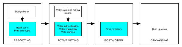 Figure 1: Major steps in the voting process when using DREs.
The shaded portions are internal to the DREs.
In this work, we mainly address voter authentication,
interaction, and vote storage.
Figure 1: Major steps in the voting process when using DREs.
The shaded portions are internal to the DREs.
In this work, we mainly address voter authentication,
interaction, and vote storage.
Pre-election setup.
The full election process incorporates many activities beyond what a
voter typically experiences in the voting booth. Although the exact
processes differ depending on the specific voting technology in
question, Figure 1 overviews the common steps for
DRE-based voting. In the pre-voting stage, election officials
prepare ballot definition files describing the parameters of the
election.
Ballot definition files can be very complex [24],
containing
not only a list of races and values indicating how many selections
a voter can make for each race, but also containing
copies of the ballots in multiple languages, audio tracks for
visually impaired voters (possibly also in multiple languages),
fields that vary by precinct, and fields that vary by the voter's
party affiliation for use in primaries.
Election officials generally use external software to help them
generate the ballot definition files.
After creating the ballot definition files, an election worker will
load those files onto the DRE voting machines.
Before polls open, election officials generally print a
"zero tape," which shows that no one cast a ballot
prior to the start of the election.
Active voting.
When a voter Alice wishes to vote, she must
first interact with election officials to prove that she is eligible
to vote.
The election officials then give her some token or mechanism to
allow her to authenticate herself to the DRE as an authorized
voter.
Once the DRE verifies the token, the DRE displays the ballot
information appropriate for Alice, e.g., the ballot might be
in Alice's native language or, for primaries, be tailored to
Alice's party affiliation.
After Alice selects the candidates she wishes to vote for,
the DRE displays a
"confirmation screen" summarizing Alice's selections.
Alice can then either
accept the list and cast her ballot, or reject it and return to
editing her selections.
Once she approves her ballot, the DRE stores the votes onto durable
storage and invalidates her token so that she cannot vote again.
Finalization & post-voting.
When the polls are closed, the DRE ensures that no further votes can be
cast and then prints a "summary tape," containing an unofficial tally of
the number of votes for each candidate.
Poll workers then transport the removable storage medium containing cast
ballot images, along with the zero tape, summary tape, and other materials,
to a central facility for tallying.
During the canvass, election officials accumulate vote totals and
cross-check the consistency of all these records.
Additional steps.
In addition to the main steps above, election officials can employ
various auditing and testing procedures to check for malicious
behavior. For example, some jurisdictions use parallel testing,
which involves sequestering a few
machines, entering a known set of ballots, and checking whether
the final tally matches the expected tally.
Also, one could envision repeating the vote-tallying process
with a third-party tallying application, although we are unaware of
any instance where this particular measure has been used in practice.
While these additional steps can help detect problems,
they are by no means sufficient.
3 Goals and assumptions
Security goals.
For clarity, in the body of this paper we focus on enabling
efficient verification
of Properties 1 and 2
(see Section 1), though we
hope to enable the efficient verification of other properties
as well.
Property 1 reflects a privacy goal: an adversary should
not be able to learn any information about how a voter voted besides
what is revealed by the published election
totals. Property 2 reflects an integrity
goal: even in the presence of an
adversary, the
DRE should
record the voter's vote exactly as the voter wishes. Further, an
adversary should not be able to undetectably alter the vote once it
is stored. We wish to
preserve these properties against the classes of
adversaries
discussed below.
Wholesale and retail attacks. A wholesale attack is one
that, when mounted, has the potential of affecting a broad number of
deployed DREs.
A classic example might be a software engineer at a
major DRE manufacturer inserting malicious logic into her company's
DRE software.
Prior work has provided evidence that this
it is a concern for real elections [3].
Such an attack could have nationwide impact and could compromise
the integrity of entire elections, if not detected.
Protecting against such wholesale attacks is one of our
primary goals.
In contrast,
a retail attack is one restricted to a small number of DREs or a
particular polling location. A classic retail attack might be a
poll worker stuffing ballots in a paper election, or selectively
spoiling ballots for specific candidates.
Classes of adversaries.
We desire a voting system that:
- Protects against wholesale attacks
by election officials, vendors, and other insiders.
- Protects against retail attacks by insiders
when the attacks do not involve compromising the physical security
of the DRE or the polling place (e.g., by modifying the hardware or software
in the DRE or tampering with its surrounding environment).
- Protects against attacks by outsiders, e.g., voters,
when the attacks do not involve compromising physical security.
We explicitly do not consider the following possible goals:
- Protect against retail attacks by election insiders and
vendors when the attacks
do involve compromising physical security.
- Protect against attacks by outsiders, e.g., voters,
when the attacks do involve compromising physical security.
On the adversaries that we explicitly do not consider.
We explicitly exclude the last two adversaries above because we
believe that adversaries who can violate the physical security of the DRE
will always be able to subvert the operation of that DRE,
no matter how it is designed or implemented.
Also, we are less concerned about physical attacks by outsiders
because they are typically retail attacks:
they require modifying each individual voting machine one-by-one,
which is not practical to do on a large scale.
For example, to attack privacy, a poll worker could mount a camera in
the voting booth or, more challenging but still conceivable,
an outsider could use Tempest technologies to infer a voter's vote
from electromagnetic emissions [18,37].
To attack the integrity of the
voting process, a poll worker with enough resources could
replace an entire DRE with a DRE of her own. Since this attack is
possible, we also do not try to protect against a poll worker
that might selectively replace internal components in a DRE.
We assume election officials have deployed adequate physical security
to defend against these attacks.
We assume that operating procedures are adequate to prevent
unauthorized modifications to the voting machine's hardware or software.
Consequently, the problem we consider is how to ensure that the original
design and implementation are secure.
While patches and upgrades to the voting system firmware and software may
occasionally be necessary, we do not consider how to securely distribute
software, firmware, and patches, nor do we consider version control between
components.
Attentive voters.
We assume that voters are attentive.
We require voters to check that the votes shown on the confirmation screen do
indeed accurately reflect their intentions; otherwise, we will not be able
to make any guarantees about whether the voter's ballot is cast as
intended.
Despite our reliance on this assumption, we realize it may not hold
for all people. Voters are fallible and not all will properly verify their
choices.
To put it another way, our system offers voters the opportunity
to verify their vote.
If voters do not take advantage of this opportunity, we cannot help them.
We do not assume that all voters will avail themselves of this opportunity,
but we try to ensure that those who do, are protected.
4 Architecture
We focus this paper on our design and implementation of the "active
voting" phase of the election process
(cf. Figure 1). We choose to focus on this step because
we believe it to be one of the most crucial and challenging part of
the election, requiring interaction with voters and the ability to
ensure the integrity and privacy of their votes. We remark that we
attempt to reduce the trust in the canvassing phase by
designing a DRE whose output record is both privacy-preserving (anonymized)
and integrity-protected.
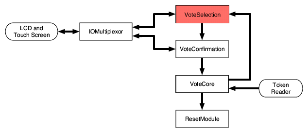 Figure 2: Our architecture, at an abstract level. For the properties we
consider, the VoteSelection module need not be trusted, so it is colored
red.
Figure 2: Our architecture, at an abstract level. For the properties we
consider, the VoteSelection module need not be trusted, so it is colored
red.
4.1 Architecture motivations
To see how specific design changes to traditional voting architectures can
help verify properties, we will go through a series of design exercises
starting from current DRE architectures and finishing at our design. The
exercises will be motivated by trying to design a system that clearly exhibits
Properties 1 and 2.
Resetting for independence.
A traditional DRE, for example the Diebold AccuVote-TS, is designed as a
single process. The functions of the DRE-validating the voter, presenting
choices, confirming those choices, storing the ballot, and administrative
functions-are all a part of the same address space.
Let us examine one particular strategy we can use to better verify
Property 1 ("memorylessness"), which requires that one voter's
selections must not influence the voting experience observed by the next
voter. Suppose after every
voter has voted, the voting machine is turned off and then restarted. This
is enough to ensure that the voting machine's memory will not contain any
information about the prior voter's
selections when it starts up.
Of course, the prior voter's selections must still be recorded on permanent
storage (e.g., on disk) for later counting, so we also
need some mechanism to prevent the machine from reading the contents of
that storage medium.
One conservative strategy would be to
simply require that any file the DRE writes to must always be
opened in write-only mode, and should never be opened for reading.
More generally, we can allow the DRE to read from some
files, such as configuration files, as long as the DRE does not have
the ability to write to them.
Thus the set of files on permanent storage are partitioned into two
classes: a set of read-only files (which cannot be modified by the DRE),
and a set of write-only files (which cannot be read by the DRE).
To summarize, our strategy for enforcing Property 1
involves two prongs:
- Ensure that a reboot is always triggered after a voter ends their
session.
- Check every place a file can be opened to ensure that data files are
write-only, and configuration files are read-only.
There must still be a mechanism to prevent the DRE from overwriting
existing data, even if it cannot read that data.
We introduce a separate component whose sole job is to manage the reset
process. The BallotBox triggers the ResetModule after a ballot is
stored. The reset module then reboots a large portion of the DRE and manages the startup
process. We use a separate component so that it is simple to audit the
correctness of the ResetModule .
We emphasize this design strategy is not the only way
to verify this particular property.
Rather, it is one technique we can implement that reduces the problem
of enforcing Property 1 to the problem of enforcing
a checklist of easier-to-verify conditions that suffice to ensure
Property 1 will always hold.
Isolation of confirmation process.
In considering Property 2, which requires the voter's consent
to cast in order for the ballot to be stored,
we will again see how modifying the
DRE's architecture in specific ways can help verify correctness of this
property.
The consent property in consideration requires auditors to confidently reason
about the casting procedures. An auditor (perhaps using program analysis
tools) may have an easier time reasoning about the casting process if it is
isolated from the rest of the voting process. In our architecture, we take
this approach in combining the casting and confirmation process, while
isolating it from the vote selection functionality of the DRE. With a careful
design, we only need to consider this sub-portion to verify
Property 2.
From our DRE design in the previous section, we introduce a new component,
called the VoteConfirmation module. With this change, the voter first
interacts with a VoteSelection module that presents the ballot choices. After
making their selections, control flow passes to the VoteConfirmation module
that performs a limited role: presenting the voter's prior selections and then
waiting for the voter to either 1) choose to modify their selections, or 2)
choose to cast their ballot. Since the VoteConfirmation module has limited
functionality, it only needs limited support for GUI code; as we show in
Section 6.1 we can more easily
analyze its correctness since its scope is limited. If the voter decides to
modify the ballot, control returns to the VoteSelection module.
Note the voter interacts with two separate components: first the VoteSelection
component and then VoteConfirmation . There are two ways to mediate the
voter's interactions with the two components: 1) endow each component with its
own I/O system and screen; 2) use one I/O system and a trusted I/O
"multiplexor" to manage which component can access the screen at a time. The
latter approach has a number of favorable features. Perhaps the most important
is that it preserves the voter's experience as provided by existing DRE
systems. A voting machine with two screens requires voters to change their
voting patterns, and can introduce the opportunity for confusion or even
security vulnerabilities. Another advantage is cost: a second screen adds
cost and complexity. One downside is that we must now verify properties about
the IOMultiplexor . For example, it must route the input and output to the
proper module at the appropriate times.
In the the final piece of our architecture, we introduce a VoteCore
component. After the voter interacts with the VoteSelection system and
then the VoteConfirmation module to approve their selection,
the VoteCore component stores the ballot on
indelible storage in its BallotBox and then cancels the voter's
authentication token. Then, as we described above, it initiates a reset
with the ResetModule to clear the state of all modules.
Let us return to our original property: how can we verify that a
ballot can only be cast with the voter's approval? With our architecture,
it suffices to verify that:
- A ballot can only enter the VoteCore through the VoteConfirmation module.
- The VoteCore gives the voter the opportunity to review the exact contents of the ballot.
- A ballot can only be cast if the voter unambiguously signals
their intent to cast.
To prove the last condition, we add
hardware to simplify an auditor's understanding of the system, as
well as to avoid calibration issues with the touch screen interface.
A physical cast
button, enabled only by the confirmation module, acts as a gate to stop the
ballot between the VoteSelection and VoteCore modules. The software in the
VoteConfirmation module does not send the ballot to the VoteCore
until the CastButton is
depressed; and, since it is enabled only in the VoteConfirmation
module, it is
easy to gain assurance that the ballot cannot be cast without the voter's
consent. Section 6.1 will show how we achieve this property based on
the code and architecture.
There is a danger if we must adjust the system's architecture to meet each
particular security property: a design meeting all security properties may be
too complex. However, in Section 8, we discuss other
security properties and sketch how we can verify them with the current
architecture. Isolating the confirmation process is a key insight that
can simplify verifying other properties. The confirmation process is at the
heart of many properties, and a small, easily understood confirmation
process helps not just in verifying Property 2.
4.2 Detailed module descriptions
Voter authentication.
After a voter signs in at a polling station, an election official
would give that voter a voting token. In our implementation, we use
a magnetic stripe card, but the token could also be a smartcard or a
piece of paper with a printed security code. Each voting token is valid
for only one voting machine. To begin voting,
the voter inserts the token into the designated voting machine.
The VoteCore
module reads the contents of the token and verifies
that the token is designated to work on this
machine (via a serial number check),
is intended for this particular election,
has not been used with this machine before,
and is signed using some public-key signature scheme.
If the verification is successful,
the VoteCore module communicates the contents of
the voting token to the VoteSelection module.
Vote selection.
The VoteSelection module parses the ballot definition file and
interacts with the voter, allowing the voter to select
candidates and vote on referenda.
The voting token indicates which ballot to use,
e.g., a Spanish ballot
if the voter's native language is Spanish or a Democratic ballot if
the voter is a Democrat voting in a primary.
The VoteSelection module is intended to follow the rules outlined in
the ballot definition file, e.g., allowing the voter to choose up to three
candidates or to rank the candidates in order of preference.
Of course, the VoteSelection module is untrusted and may contain
malicious logic, so there is no guarantee that it operates as intended.
The VoteSelection
module interacts with the voter via the IOMultiplexor .
Vote confirmation.
After the voter is comfortable with her votes, the VoteSelection
module sends a description of the voter's preferences to the
VoteConfirmation module. The VoteConfirmation module
interacts with the voter via the IOMultiplexor , displaying a summary
screen indicating the current selections and prompting the
voter to approve or reject this ballot. If the voter approves, the
VoteConfirmation module sends the ballot image6 to
the VoteCore module so it can be recorded.
The VoteConfirmation module is constructed so that the data that the
VoteConfirmation module sends to the VoteCore module is exactly
the data that it received from the VoteSelection module.
Storing votes and canceling voter authentication tokens.
After receiving a description of the votes from the
VoteConfirmation module, the VoteCore atomically stores the
votes and cancels the voter authentication token.
Votes are stored on a durable,
history-independent, tamper-evident, and subliminal-free vote
storage mechanism [25].
By "atomically," we mean that once the VoteCore component begins
storing the votes and canceling the authentication token, it will
not be reset until after those actions complete.
After those
actions both complete, the VoteCore will trigger a reset by
sending a message to the ResetModule .
Looking ahead, the only other occasion
for the ResetModule to trigger a reset is when requested by
VoteCore in response to a user wishing to cancel her voting session.
Cleaning up between sessions.
Upon receiving a signal from the VoteCore , the ResetModule
will reset all the other components.
After those components awake from the reset, they will inform the
ResetModule .
After all components are awake,
the ResetModule tells all the components to start, thereby
initiating the next voting session and allowing the next voter to vote.
We also allow the VoteCore module to trigger a reset via the ResetModule
if the voter decides to cancel their voting process; when a voter triggers
a reset in this way,
the voter's authentication token is not canceled and the voter can use
that token to vote again on that machine at a later time.
Although the VoteCore has access to
external media to store votes and canceled
authentication tokens, all other state in this component is reset.
Enforcing a trusted path between the voter and the VoteConfirmation module. Although the above
discussion only mentions the IOMultiplexor in passing, the
IOMultiplexor plays a central role in the security of our design.
Directly connecting the LCD and touch screen to
both the VoteSelection module and the VoteConfirmation module
would be unsafe:
it would allow
a malicious VoteSelection module to retain control of the
LCD and touch screen forever and display a spoofed confirmation screen,
fooling the voter into thinking she is interacting with
the trusted VoteConfirmation module when she is actually
interacting with malicious code.
The IOMultiplexor mediates access to the LCD and touch screen to prevent
such attacks.
It enforces the invariant that only one module
may have control over the LCD and touch screen at a time: either
VoteConfirmation or VoteSelection may have control, but not both.
Moreover, VoteConfirmation is given precedence: if it requests control,
it is given exclusive access and VoteSelection is locked out.
This allows our system to establish a trusted path
between the voter interface and the VoteConfirmation module.
4.3 Hardware-enforced separation
Our architecture requires components to be protected from each other, so that
a malicious VoteSelection component cannot tamper with or observe the state
or code of other components.
One possibility would be to use some form of software isolation, such as
putting each component in a separate process (relying on the OS for
isolation), in a separate virtual machine (relying on the VMM), or in a
separate Java applet (relying on the JVM).
Instead, we use hardware isolation as a simple method for achieving
strong isolation.
We execute each module on its own microprocessor (with its own CPU,
RAM, and I/O interfaces).
This relies on physical isolation in an intuitive way:
if two microprocessors are not
connected by any communication channel, then they cannot directly affect each other.
Verification of the interconnection topology of the components in our
architecture consequently reduces to verifying the physical separation of
the hardware and verifying the interconnects between them.
Historically, the security community has focused primarily on software
isolation because hardware isolation was viewed as prohibitively
expensive [32].
However, we argue that the price of a microprocessor has fallen dramatically
enough that today hardware isolation is easily affordable, and we believe the
reduction in complexity easily justifies the extra cost.
With this approach to isolation, the communication elements between
modules acquire special importance, because they determine the way that
modules are able to interact.
We carefully structured our design to simplify the connection topology
as much as possible.
Figure 3 summarizes the interconnectivity
topology, and we describe several key aspects of our design below.
We remark that when multiple hardware components are used, one
should ensure that the same versions of code run on each component.
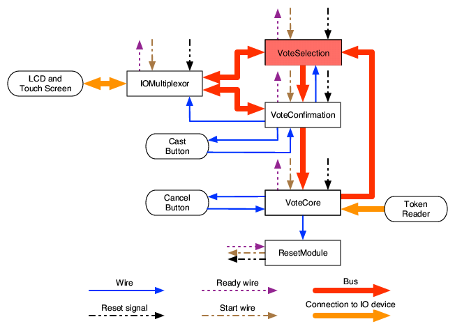 Figure 3: Our architecture, showing the hardware communication elements.
Buses and wires.
Our hardware-based architecture employs two types of communication
channels: buses and wires.
Buses provide high-speed unidirectional
or bidirectional communication between multiple components.
Wires are a simple signaling element with one bit of state;
they can be either high or low, and typically are used
to indicate the presence or absence of some event.
Wires are unidirectional: one component (the sender)
will set the value of a wire but never read it, and the other
component (the receiver) will read the value of the wire but never set it.
Wires are initially low, and can be set, but not cleared; once a wire
goes high, it remains high until its controlling component is reset.
We assume that wires are reliable but buses are potentially unreliable.
To deal with dropped or garbled messages without introducing too much
complexity, we use an extremely simple communication protocol.
Our protocol is connectionless and does not contain any in-band signaling
(e.g., SYN or ACK packets).
When a component in our architecture wishes to
transmit a message, it will repeatedly send that message over the bus
until it is reset or it receives an out-of-band signal
to stop transmitting. The sender appends a hash of the message to the
message.
The receiver accepts the first message with a valid hash, and then
acknowledges receipt with an out-of-band signal.
This acknowledgment might be conveyed by changing a wire's value
from low to high, and the sender can poll this wire to identify when to
stop transmitting.
Components that need replay protection can add a sequence number to their
messages.
Using buses and wires. We now describe how to instantiate
the communication paths in our high-level design from
Section 4.2 with buses and wires.
Once the
VoteCore module reads a valid token, it
repeatedly sends the data on the token to VoteSelection until it receives a
message from VoteConfirmation . After storing the vote and
canceling the authentication token, the VoteCore module triggers
a reset by setting its wire to the ResetModule high.
To communicate with the voter, the VoteSelection component
creates a bitmap of an image, packages that image into a message , and
repeatedly sends that message to the IOMultiplexor .
Since the VoteSelection module may send many images, it includes
in each message a sequence number; this sequence number does not change
if the image does not change.
Also included in the message is a list of virtual buttons,
each described by a globally unique button name and the x- and y-coordinates
of the region.
The IOMultiplexor will continuously read from its input source
(initially the VoteSelection module) and draw to the LCD
every bitmap that it receives with a new sequence number.
The IOMultiplexor also interprets inputs from the touch screen,
determines whether the inputs correspond to a virtual button
and, if so, repeatedly writes the name of the region to the
VoteSelection module until it has new voter input. Naming the
regions prevents user input on one screen from being interpreted as input
on a different screen.
When the voter chooses to proceed from the vote selection phase
to the vote confirmation phase, the VoteConfirmation module will
receive a ballot from the
VoteSelection module. The VoteConfirmation module
will then set its wire to the
IOMultiplexor high. When the IOMultiplexor detects this wire
going high, it will empty all its input and output bus buffers,
reset its counter for messages from the VoteSelection module, and
then only handle input and output for the VoteConfirmation
module (ignoring any messages from VoteSelection ).
If the VoteConfirmation module determines that the user
wishes to return to the VoteSelection module and edit her votes,
the VoteConfirmation module will set its wire to the
VoteSelection module high. The VoteSelection module will then
use its bus to VoteConfirmation to repeatedly acknowledge that
this wire is high. After receiving this acknowledgment, the
VoteConfirmation module will reset itself, thereby clearing all
internal state and also lowering its wires to the IOMultiplexor
and VoteSelection modules. Upon detecting that this wire returns
low, the IOMultiplexor will clear all its input and output
buffers and return to handling the input and output for
VoteSelection .
The purpose for the handshake between the VoteConfirmation module
and the VoteSelection module is to prevent the
VoteConfirmation module from resetting and then immediately
triggering on the receipt of the voter's previous selection (without
this handshake, the VoteSelection module would continuously send
the voter's previous selections, regardless of whether
VoteConfirmation reset itself).
4.4 Reducing the complexity of trusted components
We now discuss further aspects of our design that facilitate the
creation of implementations with minimal trusted code.
Resets.
Each module (except for the ResetModule ) interacts with the
ResetModule via three wires, the initial values of which are all low:
a ready wire controlled by the
component and reset and start wires controlled by the
ResetModule .
The purpose of
these three wires
is to coordinate resets to avoid a situation where
one component believes that it is handling the
i-th voter while another component believes that it is handling
the (i+1)-th voter.
The actual interaction between the wires is as follows.
When a component first
boots, it waits to complete any internal initialization steps and
then sets the ready wire high. The component then blocks
until its start wire goes high. After the
ready wires for all components connected to the
ResetModule go high, the ResetModule sets each component's
start wire high, thereby allowing all components to proceed
with handling the first voting session.
Upon completion of a voting session, i.e., after receiving a signal
from the VoteCore component, the ResetModule sets each
component's reset wire high. This step triggers each
component to reset. The ResetModule keeps the reset
wires high until all the component ready wires go low,
meaning that the components have stopped executing. The
ResetModule subsequently sets the reset wire low,
allowing the components to reboot. The above process with the
ready and start wires is then repeated.
Cast and cancel buttons.
Our hardware architecture uses two physical buttons, a cast button
and a cancel button. These buttons directly connect the user
to an individual component, simplifying the task of establishing a trusted
path for cast and cancel requests.
Our use of a hardware button (rather than a user interface element
displayed on the LCD) is intended to give voters a way to know
that their vote will be cast.
If we used a virtual cast button,
a malicious VoteSelection module could draw a spoofed
cast button on the LCD
and swallow the user's vote, making the voter think that they
have cast their vote when in fact nothing was recorded and leaving the
voter with no way to detect this attack. In contrast, a physical cast button allows attentive voters
to detect these attacks (an alternative might be to use a physical
"vote recorded" light in the VoteCore ).
Additionally, if we used a virtual cast button,
miscalibration of the touch screen could trigger
accidental invocation of the virtual cast button against the voter's wishes.
While calibration issues may still affect the ability of a
user to scroll through a multi-screen confirmation process, we
anticipate that such a problem will be easier to recover from than
touch screen miscalibrations causing the DRE to incorrectly store
a vote.
To ensure that a malicious VoteSelection module does not
trick the user into pressing the cast button prematurely, the
VoteConfirmation module will only enable the cast button after it
detects that the user paged through all the vote confirmation screens.
We want voters to be able to cancel the voting process at any time,
regardless of whether they are interacting with the VoteSelection
or VoteConfirmation modules. Since the VoteSelection module
is untrusted, one possibility would be to have the IOMultiplexor
implement a virtual cancel button or conditionally pass data to the
VoteConfirmation module even when the VoteSelection module is
active. Rather than introduce these complexities, we chose to have
the VoteCore module handle cancellation via a physical cancel button.
The cancel button is enabled (and physically lit by an internal
light) until the VoteCore begins the process of storing a ballot and
canceling an authentication token.
5 Prototype implementation
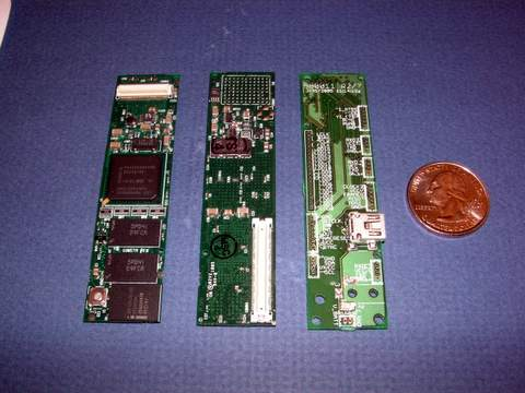 Figure 4: We show the front and back of a gumstix as well as
an expansion board through which the GPIO and serial ports are
soldered. The quarter gives an indication of the physical size of these
components.
Figure 4: We show the front and back of a gumstix as well as
an expansion board through which the GPIO and serial ports are
soldered. The quarter gives an indication of the physical size of these
components.
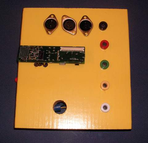 Figure 5: The mounting board for a single
component. It contains three serial ports (along the top), 4 GPIO pins and a
ground pin (along the right side), as well as a gumstix processor board
mounted atop an expansion board.
Figure 5: The mounting board for a single
component. It contains three serial ports (along the top), 4 GPIO pins and a
ground pin (along the right side), as well as a gumstix processor board
mounted atop an expansion board.
To evaluate the feasibility of the architecture presented in
Section 4, we built a prototype implementation.
Our prototype uses off-the-shelf "gumstix connex 400xm" computers.
These computers measure 2cm by 8cm in size, cost $144 apiece,
and contain an Intel XScale PXA255 processor with a 400 MHz StrongARM core,
64 MB of RAM, and 16 MB of flash for program storage.
We enable hardware isolation by using
a separate gumstix for each component in our architecture.
We do not claim that the gumstix would be the best way to engineer
an actual voting system intended for use in the field.
However, the gumstix have many advantages as a platform for prototyping
the architecture.
In conjunction with an
equally sized expansion board, the processors support three external RS-232
serial ports, which transmit bidirectional data at 115200 kbps.
We use serial ports as our buses.
Additionally, each gumstix supports many
general purpose input/output (GPIO) registers,
which we use for our wires.
Finally, the XScale processor supports an LCD and touch screen interface.
The gumstix platform's well-designed toolchain and software environment
greatly simplified building our prototype.
The gumstix, and our prototype, use a minimal Linux distribution
as their operating system. Our components are written in Java and run on the
Microdoc J9 Java VM; its JIT provides a significant speed advantage
over the more portable JamVM Java interpreter.
Our choice of Java is twofold: it is a type-safe
language and so prevents a broad range of exploits; secondly,
several program verification tools are available for verifying invariants
in Java code [8,19].
C# is another natural language choice since it too is type-safe and
the Spec# [5] tool could aid in verification,
but C# is not supported as well
on Linux.
We view a rich stable of effective verification
tools to be just as important as type-safety in choosing the implementation
language since
software tools can improve confidence in the voting software's
correctness. Both can eliminate large classes of bugs.
5.1 Implementation primitives
Our architecture requires implementations of two separate communications
primitives:
buses and wires.
It is
straightforward to implement buses using serial ports on the gumstix.
To do so, we expose
connectors for the serial ports via an
expansion board connected to the main processor. Figures 4
and 5
show an example of such an expansion board.
We additionally disable the getty terminal running on the serial ports
to allow conflict free use of all three serial ports.
The PXA255 processor has 84 GPIO pins, each controlled by registers;
we implement wires using these GPIOs.
A few of the pins are exposed on our expansion board and allow two
components to be interconnected via their exposed GPIO pins. Each
GPIO pin can be set in a number of modes. The processor can set the
pin "high" so that the pin has a 3.3 volt difference between the
reference ground; otherwise, it is low and has a 0 voltage
difference between ground. Alternatively, a processor can poll the
pin's state. To enforce the unidirectional communication property,
particularly when a single wire is connected to more than two GPIOs,
we could use a diode, which allows current to flow in only one
direction 7.
We currently rely on software to enforce that once a GPIO is set high,
it cannot ever be set low without first restarting the process; this
is a property one could enforce in hardware via a latch, though our
current prototype does not do so yet.
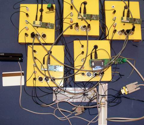 Figure 6: A picture of our prototype implementation.
There is one board for each
component in the system. The magnetic swipe card (along the left) is used for
authentication, while the cast button is in the upper left component.
Figure 6: A picture of our prototype implementation.
There is one board for each
component in the system. The magnetic swipe card (along the left) is used for
authentication, while the cast button is in the upper left component.
In addition to the GPIOs, the PXA255 exposes an NRESET pin.
Applying a 3.3v signal to the NRESET pin causes
the processor to immediately halt execution; when the signal is removed, the
processor begins in a hard boot sequence.
The gumstix are able to reboot in under
10 seconds without any optimizations, making the NRESET pin nearly
ideal to clear a component's state during a reset.
Unfortunately, the specifics of the
reboot sequence causes slight problems for our usage.
While the NRESET wire is held high, the GPIO pins are also high.
In the case where one
component reboots before another (or where selective components are reboot),
setting the GPIOs high will inadvertently propagate a signal along the wire to
the other components.
Ideally, the pins would be low during reset.
We surmise that designing a chip for our ideal reset behavior would not be
difficult given sufficient hardware expertise. Since the microprocessors in
our platform do not exhibit our ideal behavior,
in our prototype
we have a separate daemon connected
to an ordinary GPIO wire that stops the Java process running the component
code
when the reset pin goes high and then resets all wire state to low.
The daemon starts a new
component process when the signal to its reset pin is removed.
This is just a way of emulating, in software, the NRESET semantics we
prefer. Of course, a production-quality implementation would enforce
these semantics in trusted hardware.
We use a Kanecal KaneSwipe GIT-100 magnetic card reader for authorizing voters
to use the machine.
A voter would receive a card with authentication information on it from
poll workers upon signing in. The voter cannot forge the authentication
information (since it contains a public key signature), but can use it to vote
once on a designated DRE.
The reader has an RS-232
interface, so we are able to use it in conjunction with the serial port on
the gumstix.
Finally, our implementation of the VoteCore component
uses a compact flash card to store cast ballot images and invalid
magcard identifiers.
Election officials can remove the flash card and transport it to county
headquarters after the close of polls.
A deployed DRE might use stronger privacy-protection mechanisms, such
as a history-independent, tamper-evident, and subliminal-free
data structure [25].
For redundancy,
we expect a deployed DRE to also store multiple copies of the votes on
several storage devices.
A full implementation of the VoteSelection component would likely
also use some kind of removable storage device to store the ballot
definition file.
In our prototype, we hard-code a sample ballot definition file into the
VoteSelection component. This suffices for our purposes in gauging the
feasibility of other techniques.
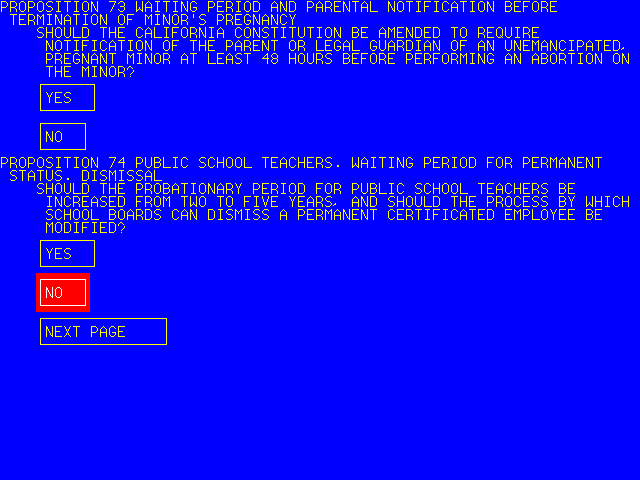 Figure 7: The right image shows a screenshot of the VoteSelection component
displaying referenda from the November 2005 election in Berkeley, CA.
We flipped a coin to choose the response shown on this screen.
Figure 7: The right image shows a screenshot of the VoteSelection component
displaying referenda from the November 2005 election in Berkeley, CA.
We flipped a coin to choose the response shown on this screen.
Our prototype consists of five component boards wired together in accordance
with Figure 3. We implement all of the
functionality except for the cancel button. See
Figure 6 for a picture showing the five components and
all of their interconnections. Communication uses
physical buses and wires. The I/O multiplexer, after each update operation,
sends an image over a virtual bus connected (connected via the USB network) to
the PC for I/O. It sends the compressed image it would ordinarily blit to the
framebuffer to the PC so that the PC can blit it to its display. The gumstix
only recently supported LCD displays,
and we view our PC display as an interim solution. The
additional software complexity for using the LCD is minimal as it only
requires blitting an image to memory.
Figure 7 shows our voting software running on the
gumstix. We used ballot data from the November 2005 election in Alameda
County, California.
6 Evaluation
6.1 Verifying the desired properties
|
1 grabio.set();
2 ... UPDATE DISPLAY ...
3 castenable.set();
4 if (cast.isSet()) {
5 while (true) {
6 toVoteCore.write(ballot);
7 }
8 }
Confirm.java
|
|
|
1 byte [] ballot =
2 fromVoteConf.read();
3 if (ballot != null) {
4 ... INVALIDATE VOTER TOKEN ...
5 ballotbox.write (ballot);
6 while (true) {
7 resetWire.set();
8 }
9 }
VoteCore.java
|
|
Figure 8: Code extracts from the VoteConfirmation and VoteCore modules,
respectively. Examining these code snippets with the connection topology
helps us gain assurance that the architecture achieves
Properties 1 and 2.
Property 1.
Recall that to achieve "memorylessness" we must be able
to show the DRE is always reset after a voter has finished using the machine,
and the DRE only opens a given file read-only or write-only, but not both. To
show that the DRE is reset after storing a vote, we examine a snippet of the
source code from VoteCore.java, the source code for the VoteCore module
in Figure 8. In line 7, after storing the ballot into the ballot
box, the VoteCore module continuously raises the reset wire high.
Looking at the connection diagram
from Figure 3, we note the reset wire
terminates at the ResetModule and induces it to restart all
components in the system. Further inspecting code not reproduced in
Figure 8 reveals
the only reference to the ballotbox is in the constructor and in line
5, so writes to it are confined to line 5.
Finally, we need merely examine every file open call to
make sure they are either read-only or write only. In practice, we can
guarantee this by ensuring writable files are append-only, or for more
sophisticated vote storage mechanisms as proposed by Molnar et al., that the
storage layer
presents a write-only interface to the rest of the DRE.
Property 2.
For the "consent-to-cast" property, we need to verify
two things: 1) the ballot can only enter the VoteCore through the
VoteConfirmation module, and 2) the voter's consent is required before
the ballot can leave the VoteConfirmation module.
Looking first at Confirm.java in Figure 8, the
VoteConfirmation module first ensures it has control of the
touch screen as it signals the IOMultiplexor with the "grabio" wire. It then
displays the ballot over the bus, and subsequently enables the cast
button. Examining the hardware will show the only way the wire can be enabled
is through a specific GPIO, in fact the one controlled by the "castenable"
wire. No other component in the system can enable the cast button, since it is
not connected to any other module. Similarly, no other component in the system
can send a ballot to the VoteCore module: on line 6 of Confirm.java,
the VoteConfirmation sends the ballot on a bus named "toVoteCore", which is
called the "fromVoteConf" bus in VoteCore.java. The ballot is
demarshalled on line 1. Physically
examining the hardware configuration confirms these connections, and shows the
ballot data structure can only come from the VoteConfirmation
module. Finally, in the VoteCore module, we see the only use of the
ballotbox is at line 5 where the ballot is written to the box. There are
only two references to the BallotBox in the VoteCore.java source file
(full file
not shown here),
one at the constructor site and the one shown here. Thus we can be
confident that the only way for a ballot to be passed to the BallotBox is
if a voter presses the cast button, indicating their consent.
We must also verify that the images displayed to the voter reflect the
contents of the ballot.
6.2 Line counts
| Java | C (JNI) | Total | |
| Communications | 2314 | 677 | 2991 |
| Display | 416 | 52 | 468 |
| Misc. (interfaces) | 25 | 0 | 25 |
| VoteSelection | 377 | 0 | 377 |
| VoteConfirmation | 126 | 0 | 126 |
| IOMultiplexor | 77 | 0 | 77 |
| VoteCore | 846 | 54 | 900 |
| ResetModule | 121 | 0 | 121 |
| Total | 4302 | 783 | 5085 |
Table 1: Non-comment, non-whitespace lines of code.
One of our main metrics of success is the size of the trusted computing
base in our implementation.
Our code contains
shared libraries (for communications, display, or interfaces) as well as
each of the main four modules in the TCB (VoteConfirmation , IOMultiplexor ,
VoteCore , and ResetModule ). The VoteSelection module can be excluded from
the TCB when considering Properties 1 and 2.
Also included in the TCB, but not our line count figures, are standard
libraries, operating system code, and JVM code.
In Table 1, we show the size of each trusted portion as a count
of the number of source lines of code, excluding comments and whitespace.
The communications libraries marshal and unmarshal data structures and
abstract the serial devices and GPIO pins.
The display libraries render text
into our user interface (used by the VoteConfirmation component) and
ultimately to the framebuffer.
7 Applications to VVPATs and cryptographic voting protocols
So far we've been considering our architecture in the context of a stand-alone
paperless DRE machine.
However, jurisdictions such as California
require DREs to be augmented with a voter
verified paper audit trail. In a VVPAT system, the voter is given a chance
to inspect the paper audit trail and approve or reject the printed VVPAT record.
The paper record, which remains behind glass to prevent
tampering, is stored for later recounts or audits.
VVPAT-enabled DREs greatly improve integrity protection
for non-visually impaired voters.
However, a VVPAT does not solve all problems.
Visually impaired voters who use the audio interface
have no way to visually verify the selections printed on the paper record,
and thus receive little benefit from a VVPAT.
Also, a VVPAT is only an integrity mechanism
and does not help with vote privacy.
A paper audit trail cannot prevent a malicious DRE from leaking
one voter's choices to the next voter, to a poll worker, or to some
other conspirator.
Third, VVPAT systems require careful procedural controls over the
chain of custody of paper ballots.
Finally, a VVPAT is a fall-back, and even in machines that provide a VVPAT,
one still would prefer the software to be as trustworthy as possible.
For these reasons, we view VVPAT as addressing some, but not all problems.
Our methods can be used to ameliorate some of the remaining limitations,
by providing better integrity protection for visually impaired voters,
better privacy protection for all voters,
reducing the reliance on procedures for handling paper,
and reducing the costs of auditing the source code.
Combining our methods with a VVPAT would be straightforward: the
VoteConfirmation module could be augmented with support for a printer,
and could print the voter's selections at the same time as they are
displayed on the confirmation screen.
While our architecture might be most relevant to jurisdictions that have
decided, for whatever reason, to use paperless DREs,
we expect that our methods could offer some benefits to VVPAT-enabled DREs, too.
Others have proposed cryptographic voting protocols to enhance
the security of DREs [10,16,26,27].
We note that our methods could be easily combined with those
cryptographic schemes.
8 Extensions and discussion
In addition to the properties we discussed, there are other relevant security
properties which we considered in designing our voting system. We have not rigorously
validated that the design provides these properties,
though we outline directions we
will follow to do so.
Property 3
The DRE cannot leak information through the on-disk format. Additionally,
it should be history-independent and tamper evident.
Property 3 removes the back-end tabulation system from
the trusted path. Without this property, the tabulation system may be
in the trusted path because the data input to the tabulation system may
reveal individual voter's choices. With this property, it is possible to make
the outputs of each individual DRE publicly available, and allow multiple
parties to independently tabulate the final results. We believe we can use the
techniques from Molnar et al. in implementing
Property 3 [25].
Property 4
The DRE only stores ballots the voter approves.
Property 4 refers to a few conditions. The DRE must not
change the ballot after the voter makes their selection in the VoteSelection
module; software analysis techniques could prove useful in ensuring the ballot
is not modified.
Additionally, there will need to be some auditing of the code
to ensure display routines accurately display votes to the screen.
Property 5
The ballot contains nothing more than the voter's choices.
In particular, the ballot needs to be put into a canonical form
before being stored.
Violation of Property 5 could violate the voter's privacy,
even if the voter approves the ballot. Suppose the voter's choice, "James
Polk" were stored with an extra space:
"James Polk". The voter would not likely
notice anything were amiss, but this could convey privacy leaking information
in a subliminal channel [16]. We expect software
analysis techniques could ensure that canonicalization functions are run on
all program paths.
Combined with Property 4 to ensure the ballot doesn't
change, this would help ensure the ballot is canonicalized.
We do not expect these to be an exhaustive list of the desirable security
properties; rather, they are properties that we believe are important and that
we can easily achieve with this architecture without any changes.
Minimizing the underlying software platform.
Our prototype runs under an embedded Linux distribution that is custom
designed for the gumstix platform. Despite its relatively minimal size (4MB
binary for kernel and all programs and data), it still presents a large TCB,
most of which is unnecessary for a special-purpose voting appliance.
We expect that a serious deployment would dispense with the OS and build
a single-purpose embedded application running directly on the hardware.
For instance, we would not need virtual memory, memory protection, process
scheduling, filesystems, dual-mode operation,
or most of the other features found in general-purpose operating
systems.
It might suffice to have a simple bootloader and a thin
device driver layer specialized to just those devices that will be used
during an election.
Alternatively, it may be possible to use ideas from
nanokernels [11],
microkernels [14,31], and operating system
specialization [30] to reduce the
operating system and accordingly the TCB size.
Deploying code.
Even after guaranteeing the software is free of vulnerabilities, we must also
guarantee that the image running on the components is the correct image.
This is not an easy problem, but the research community has begun to address
the challenges. SWATT [34] is
designed to validate the code image on embedded platforms, though their model
does not allow for CPUs with virtual memory, for example.
TCG and NGSCB
use a secure hardware co-processor to achieve the same ends, though deploying
signed and untampered code to devices still requires much work.
Additionally, a human must then check that all components are running
the latest binary and must ensure that the binaries are compatible with each
other - so that a version 1.0 VoteCore is not running with a version 1.1
IOMultiplexor module, for example.
This concern is orthogonal to ours, as even current voting
machines must deal with versioning.
It illustrates one more challenge in deploying a secure voting system.
9 Related work
There has been a great deal of work on
high-assurance and safety-critical systems,
which are designed, implemented, and tested to achieve
specific safety, reliability, and security properties.
We use many classic techniques from that field,
including minimization of the size of the TCB and decomposing the
application into clearly specified components.
One contribution of this paper is that we show in detail how
those classic techniques may be applied in the e-voting context.
Modularity is widely understood to be helpful in building high-reliability
systems.
Deep space applications often use multiple components for reliability
and fault tolerance [41].
Telephone switches use redundant components to upgrade software
without loss of availability [41]. In avionics,
Northrop Grumman has proposed an
architecture for future avionics systems
suitable to the Department of Defense's Joint Vision
2020 [39]. Their MLS-PCA architecture is intended to
support tens to hundreds of thousands of separate processors.
MLS-PCA uses isolation for several purposes, including
mission flexibility, multi-level security when
interoperating with NGOs, and
reduction in the amount of trusted software over traditional federated
architectures. Of these reasons, the last is most related to our setting.
Others have articulated composibility of security as one of the key
challenges in applying modularity to the security setting [21].
Rebooting is widely recognized in industry as a useful way to
prevent and rectify errors [9].
Rebooting returns the system to its original state, which is often a
more reliable one.
Others use preventative rebooting to mitigate resource
leaks and Heisenbugs [15].
In contrast, our work uses rebooting
for what we believe is a new purpose: privacy. Prior work focuses on
availability and recoverability, while we use it to simplify our task in
verifying privacy preserving properties.
The Starlight Interactive Link is a hardware device that allows a workstation
trusted with secret data to safely interact with an unclassified
network [2]. The Starlight Interactive Link acts as a data diode.
A chief concern is secret data leaking onto the
untrusted network. Many of these ideas led to the design of our IOMultiplexor .
Our design shares similarities with existing DRE voting machines from major
vendors, such as
Diebold, Hart Intercivic, Sequoia Voting Systems, and Election Systems and
Software. A criticism of the machines, however, is that people
must trust the software running on the machines since the voter cannot be sure
their vote was properly recorded. Rebecca Mercuri has called for vendors to
augment DRE machines with a voter verified paper audit trail
(VVPAT) [22,23]. In this DRE variant, the voter must
approve a paper copy of their selections that serves as the permanent record.
The paper copy is typically held behind glass so the voter cannot tamper with
it. Even in spite of malicious software, the paper copy accurately reflects
the voter's selections.
The principle of isolation for systems is well established [4,7,12,20,28,31,32,35,36,40]. Isolation has been proposed as a technique to improve security in
two existing voting systems.
The FROGS and Pnyx.DRE systems both separate the
vote selection process from vote confirmation [1,6].
However, FROGS significantly
alters the voting experience while it is not clear the Pnyx.DRE was designed
for verification nor does it provide our privacy protections.
Finally, Hall discusses the impact of disclosing the source for voting
machines for independent audit [13].
10 Conclusions
Democracy deserves the best efforts that computer scientists can deliver in
producing accurate and verifiable voting systems. In this work, we have
proposed better DRE based voting designs, whether VVPAT-enabled or not.
In both cases, our architecture provides
stronger security properties than current voting systems.
Our approach uses hardware to isolate components from each other
and uses reboots to guarantee voter privacy.
In particular,
we have shown how isolating the VoteSelection module, where much of the
hairiness of a voting system resides, into its own module can
eliminate a great deal of complex code from the TCB.
Though isolation is not a novel idea,
the way we use it to improve the security of DREs is new.
This work shows that it is possible to improve existing DREs without
modifying the existing voter experience or
burdening the voter with additional checks or procedures.
The principles and techniques outlined here show that there is a better way to
design voting systems.
Acknowledgments
We thank David Jefferson for early discussions that led to this work. Umesh
Shankar, Chris Karlof, Rob Johnson, and Mike Reiter
provided invaluable feedback on the
presentation, organization, and provided great insight into the thinking and
organization of the work. We thank Matt Bishop and David Molnar for helpful
discussions about related works.
References
- [1]
-
Auditability and voter-verifiability for electronic voting terminals.
https://www.scytl.com/docs/pub/a/PNYX.DRE-WP.pdf, December 2004.
White paper.
- [2]
-
M. Anderson, C. North, J. Griffin, R. Milner, J. Yesberg, and K. Yiu.
Starlight: Interactive Link.
In Proceedings of the 12th Annual Computer Security
Applications Conference (ACSAC), 1996.
- [3]
-
J. Bannet, D. W. Price, A. Rudys, J. Singer, and D. S. Wallach.
Hack-a-vote: Demonstrating security issues with electronic voting
systems.
IEEE Security and Privacy Magazine, 2(1):32-37, Jan./Feb.
2004.
- [4]
-
P. Barham, B. Dragovic, K. Fraser, S. Hand, T. Harris, A. Ho, R. Neugebauer,
I. Pratt, and A. Warfield.
Xen and the art of virtualization.
In Proceedings of the 19th ACM Symposium on Operating
Sstems Principles (SOSP 2003), October 2003.
- [5]
-
M. Barnett, K. R. Leino, and W. Schulte.
The Spec# programming system: An overview.
In Proceedings of Construction and Analysis of Safe, Secure and
Interoperable Smart Devices (CASSIS), 2004.
- [6]
-
S. Bruck, D. Jefferson, and R. Rivest.
A modular voting architecture ("Frogs").
https://www.vote.caltech.edu/media/documents/wps/vtp_wp3.pdf,
August 2001.
Voting Technology Project Working Paper.
- [7]
-
E. Bugnion, S. Devine, and M. Rosenblum.
Disco: Running commodity operating systems on scalable
multiprocessors.
In Proceedings of the 16th ACM Symposium on Operating
Systems Principles (SOSP), October 1997.
- [8]
-
L. Burdy, Y. Cheon, D. Cok, M. Ernst, J. Kiniry, G. Leavens, K. R. Leino, and
E. Poll.
An overview of JML tools and applications.
International Journal on Software Tools for Technology Transfer
(STTT), 7(3):212-232, June 2005.
- [9]
-
G. Candea, S. Kawamoto, Y. Fujiki, G. Friedman, and A. Fox.
Microreboot - a technique for cheap recovery.
In 6th Symposium on Operating System Design and Implementation
(OSDI), December 2004.
- [10]
-
D. Chaum.
Secret-ballot receipts: True voter-verifiable elections.
IEEE Security & Privacy Magazine, 2(1):38-47, Jan.-Feb.
2004.
- [11]
-
D. Engler, M. F. Kaashoek, and J. O'Toole.
Exokernel: An operating system architecture for application-level
resource management.
In Proceedings of the 15th ACM Symposium on Operating
Systems Principles (SOSP), October 1995.
- [12]
-
I. Goldberg, D. Wagner, R. Thomas, and E. Brewer.
A secure environment for untrusted helper applications: Confining the
wily hacker.
In Proceedings of the 6th USENIX Security Symposium,
August 1996.
- [13]
-
J. Hall.
Transparency and access to source code in e-voting.
Unpublished manuscript.
- [14]
-
G. Heiser.
Secure embedded systems need microkernels.
USENIX ;login, 30(6):9-13, December 2005.
- [15]
-
Y. Huang, C. Kintala, N. Kolettis, and N. D. Fulton.
Software rejuvenation: Analysis, module and applications.
In Twenty-Fifth International Symposium on Fault-Tolerant
Computing, 1995.
- [16]
-
C. Karlof, N. Sastry, and D. Wagner.
Cryptographic voting protocols: A systems perspective.
In Fourteenth USENIX Security Symposium, August 2005.
- [17]
-
T. Kohno, A. Stubblefield, A. D. Rubin, and D. S. Wallach.
Analysis of an electronic voting system.
In IEEE Symposium on Security and Privacy, pages 27-40, May
2004.
- [18]
-
M. Kuhn.
Optical time-domain eavesdropping risks of CRT displays.
In IEEE Symposium on Security and Privacy, May 2002.
- [19]
-
G. Leavens and Y. Cheon.
Design by contract with JML.
ftp://ftp.cs.iastate.edu/pub/leavens/JML/jmldbc.pdf.
- [20]
-
J. Liedtke.
Toward real microkernels.
Communications of the ACM, 39(9):70, September 1996.
- [21]
-
D. McCullough.
Noninterference and the composability of security properties.
In IEEE Symposium on Security and Privacy, May 1988.
- [22]
-
R. Mercuri.
Electronic Vote Tabulation Checks & Balances.
PhD thesis, School of Engineering and Applied Science of the
University of Pennsylvania, 2000.
- [23]
-
R. Mercuri.
A better ballot box?
IEEE Spectrum, 39(10):46-50, October 2002.
- [24]
-
D. Mertz.
XML Matters: Practical XML data design and manipulation for
voting systems.
https://www-128.ibm.com/developerworks/xml/library/x-matters36.html,
June 2004.
- [25]
-
D. Molnar, T. Kohno, N. Sastry, and D. Wagner.
Tamper-evident, history-independent, subliminal-free data structures
on PROM storage -or- How to store ballots on a voting machine (extended
abstract).
In IEEE Symposium on Security and Privacy, May 2006.
- [26]
-
C. A. Neff.
A verifiable secret shuffle and its application to e-voting.
In 8th ACM Conference on Computer and Communications Security
(CCS 2001), pages 116-125, November 2001.
- [27]
-
C. A. Neff.
Practical high certainty intent verification for encrypted votes.
https://www.votehere.net/vhti/documentation, October 2004.
- [28]
-
N. Provos, M. Friedl, and P. Honeyman.
Preventing privilege escalation.
In Proceedings of the 12th USENIX Security Symposium,
August 2003.
- [29]
-
RABA Innovative Solution Cell.
Trusted agent report Diebold AccuVote-TS voting system, January
2004.
- [30]
-
M. Rajagopalan, S. Debray, M. Hiltunen, and R. Schlichting.
Automated operating system specialization via binary rewriting.
Technical Report TR05-03, University of Arizona, February 2005.
- [31]
-
R. Rashid Jr., A. Tevanian, M. Young, M. Young, D. Golub, R. Baron, D. Black,
W. Bolosky, and J. Chew.
Machine-independent virtual memory management for paged uniprocessor
and multiprocessor architectures.
In Proceedings of the 2nd Symposium on Architectural Support for
Programming Languages and Operating Systems (ASPLOS), October 1987.
- [32]
-
J. Rushby.
Design and verification of secure systems.
In Proceedings of the 8th ACM Symposium on Operating Systems
Principles (SOSP), December 1981.
- [33]
-
Science Applications International Corporation (SAIC).
Risk assessment report Diebold AccuVote-TS voting system and
processes, September 2003.
- [34]
-
A. Seshadri, A. Perrig, L. van Doorn, and P. Khosla.
SWAtt: Software-based attestation for embedded devices.
In Proceedings of the IEEE Symposium on Security and Privacy,
May 2004.
- [35]
-
M. Swift, M. Annamalai, B. Bershad, and H. Levy.
Recovering device drivers.
In Proceedings of the 6th ACM/USENIX Symposium on
Operating System Design and Implementation, December 2004.
- [36]
-
M. Swift, B. Bershad, and H. Levy.
Improving the reliability of commodity operating systems.
In Proceedings of the 19th ACM Symposium on Operating
Sstems Principles (SOSP 2003), October 2003.
- [37]
-
W. van Eck.
Electromagnetic radiation from video display units: An eavesdropping
risk?
Computers & Security, 4, 1985.
- [38]
-
D. Wagner, D. Jefferson, M. Bishop, C. Karlof, and N. Sastry.
Security analysis of the Diebold AccuBasic interpreter.
California Secretary of State's Voting Systems Technology Assessment
Advisory Board (VSTAAB), February 2006.
- [39]
-
C. Weissman.
MLS-PCA: A high assurance security architecture for future
avionics.
In Proceedings of the 19th Annual Computer Security Applications
Conference (ACSAC 2003), 2003.
- [40]
-
A. Whitaker, M. Shaw, and S. Gribble.
Denali: A scalable isolation kernel.
In 10th ACM SIGOPS European Workship, September 2002.
- [41]
-
I.-L. Yen and R. Paul.
Key applications for high-assurance systems.
IEEE Computer, 31(4):35-45, April 1998.
Footnotes:
1nks@cs.berkeley.edu.
Supported by NSF CNS-0524252 and
by the Knight Foundation under a subcontract through
the Caltech/MIT Voting Technology Project.
2tkohno@cs.ucsd.edu.
Supported by NSF CCR-0208842, NSF ANR-0129617,
and NSF CCR-0093337. Part of this research was
performed while visiting the University of
California at Berkeley.
3daw@cs.berkeley.edu.
Supported by NSF CCR-0093337 and CNS-0524252.
4Note that we do allow
certain unavoidable interactions, e.g., after the ballot storage
device becomes "full,"
a voting machine
should not allow subsequent voters to vote.
5
Kohno et al.
count the total number of lines in their paper [17]; for a fair
comparison with our work, we look at source lines of code, which excludes
comments and whitespace from the final number. Hence, the numbers cited in
their paper differ from the figure we list.
6A ballot
image is merely a list of who this voter has voted for.
It need not be an actual image or picture.
7Even this may not be enough, since an actual diode does
not behave as the idealized diode we rely upon.
File translated from
TE X
by
TT H,
version 3.74.
On 11 May 2006, 22:46.
|