| ||||||||||||||||||||||||||||||||||||||||||||||||||||
4th USENIX OSDI Symposium
[Technical Program]
Operating System Management of
| ||||||||||||||||||||||||||||||||||||||||||||||||||||||||||||||||||||||||||||||
| device capacity | 3.2 GB |
|---|---|
| number of tips | 6400 |
| maximum concurrent tips | 1280 |
| sled acceleration | 803.6 m/s2 |
| sled access speed | 28 mm/s |
| constant settling time | 0.22 ms |
| spring factor | 75% |
| per-tip data rate | 0.7 Mbit/s |
| media bit cell size | 40 × 40 nm |
| bits per tip region (M × N) | 2500 × 2440 |
| data encoding overhead | 2 bits per byte |
| servo overhead per 8 bytes | 10 bits (11%) |
| command processing overhead | 0.2 ms/request |
| on-board cache memory | 0 MB |
| external bus bandwidth | 100 MB/s |
Table 1: Default MEMS-based storage device parameters. N=2440 in order to fit an integral number of 80-bit encoded sectors (with inter-sector servo) in each column of bits. The default model includes no on-board caching (or prefetching), but does assume speed-matching buffers between the tips and the external bus.
The experiments in this paper use the performance model for MEMS-based storage described in Reference [11], which includes all of the characteristics described above. Although it is not yet possible to validate the model against real devices, both the equations and the default parameters are the result of extensive discussions with groups that are designing and building MEMS-based storage devices [2, 3, 20]. We therefore believe that the model is sufficiently representative for the insights gained from experiments to be useful. Table 1 shows default parameters for the MEMS-based storage device simulator.
This performance model has been integrated into the DiskSim simulation environment [10] as a disklike storage device accessed via a SCSI-like protocol. DiskSim provides an infrastructure for exercising the device model with various synthetic and trace-based workloads. DiskSim also includes a detailed, validated disk module that can accurately model a variety of real disks. For reference, some experiments use DiskSim's disk module configured to emulate the Quantum Atlas 10K, one of the disks for which publicly available configuration parameters have been calibrated against real-world drives [8]. The Quantum Atlas 10K has a nominal rotation speed of 10,000 RPM, average seek time of 5.0 ms, streaming bandwidth of 17.3-25.2 MB/s, and average random single-sector access time of 8.5 ms [22].
Some of the experiments use a synthetically generated workload that we refer to as the Random workload. For this workload, request inter-arrival times are drawn from an exponential distribution; the mean is varied to simulate a range of workloads. All other aspects of requests are independent: 67% are reads, 33% are writes, the request size distribution is exponential with a mean of 4 KB, and request starting locations are uniformly distributed across the device's capacity.
For more realistic workloads, we use two traces of real disk activity: the TPC-C trace and the Cello trace. The TPC-C trace comes from a TPC-C testbed, consisting of Microsoft SQL Server atop Windows NT. The hardware was a 300 MHz Intel Pentium II-based system with 128 MB of memory and a 1 GB test database striped across two Quantum Viking disk drives. The trace captures one hour of disk activity for TPC-C, and its characteristics are described in more detail in Reference [23]. The Cello trace comes from a Hewlett-Packard system running the HP-UX operating system. It captures disk activity from a server at HP Labs used for program development, simulation, mail, and news. While the total trace is actually two months in length, we report data for a single, day-long snapshot. This trace and its characteristics are described in detail in Reference [25]. When replaying the traces, each traced disk is replaced by a distinct simulated MEMS-based storage device.
As is often the case in trace-based studies, our simulated devices are newer and significantly faster than the disks used in the traced systems. To explore a range of workload intensities, we replicate an approach used in previous disk scheduling work [34]: we scale the traced inter-arrival times to produce a range of average inter-arrival times. When the scale factor is one, the request inter-arrival times match those of the trace. When the scale factor is two, the traced inter-arrival times are halved, doubling the average arrival rate.
An important mechanism for improving disk efficiency is deliberate scheduling of pending requests. Request scheduling improves efficiency because positioning delays are dependent on the relative positions of the read/write head and the destination sector. The same is true of MEMS-based storage devices, whose seek times are dependent on the distance to be traveled. This section explores the impact of different scheduling algorithms on the performance of MEMS-based storage devices.
 |
 |
|---|---|
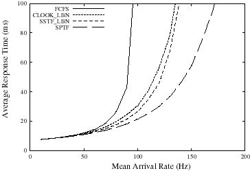
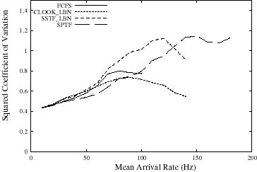
| (a) Average response times | (b) Squared coefficients of variation (s2 / m2) |
Figure 5: Comparison of scheduling algorithms for the Random workload on the Quantum Atlas 10K disk.
Many disk scheduling algorithms have been devised and studied over the years. Our comparisons focus on four. First, the simple FCFS (first-come, first served) algorithm often results in suboptimal performance, but we include it for reference. The SSTF (shortest seek time first) algorithm was designed to select the request that will incur the smallest seek delay [4], but this is rarely the way it functions in practice. Instead, since few host OSes have the information needed to compute actual seek distances or predict seek times, most SSTF implementations use the difference between the last accessed LBN and the desired LBN as an approximation of seek time. This simplification works well for disk drives [34], and we label this algorithm as SSTF LBN. The CLOOK LBN (cyclical look) algorithm services requests in ascending LBN order, starting over with the lowest LBN when all requests are "behind" the most recent request [28]. The SPTF (shortest positioning time first) policy selects the request that will incur the smallest positioning delay [14, 29]. For disks, this algorithm differs from others in that it explicitly considers both seek time and rotational latency.
For reference, Figure 5 compares these four disk scheduling algorithms for the Atlas 10K disk drive and the Random workload (Section 3) with a range of request arrival rates. Two common metrics for evaluating disk scheduling algorithms are shown. First, the average response time (queue time plus service time) shows the effect on average performance. As expected, FCFS saturates well before the other algorithms as the workload increases. SSTF LBN outperforms CLOOK LBN, and SPTF outperforms all other schemes. Second, the squared coefficient of variation (s2 / m2) is a metric of "fairness" (or starvation resistance) [30, 34]; lower values indicate better starvation resistance. As expected, CLOOK LBN avoids the starvation effects that characterize the SSTF LBN and SPTF algorithms. Although not shown here, age-weighted versions of these greedy algorithms can reduce request starvation without unduly reducing average case performance [14, 29].
Existing disk scheduling algorithms can be adapted to MEMS-based storage devices once these devices are mapped onto a disk-like interface. Most algorithms, including SSTF LBN and CLOOK LBN, only use knowledge of LBNs and assume that differences between LBNs are reasonable approximations of positioning times. SPTF, which addresses disk seeks and rotations, is a more interesting case. While MEMS-based storage devices do not have a rotational latency component, they do have two positioning time components: the X dimension seek and the Y dimension seek. As with disks, only one of these two components (seek time for disks; the X dimension seek for MEMS-based storage devices) is approximated well by a linear LBN space. Unlike disks, the two positioning components proceed in parallel, with the greater subsuming the lesser. The settling time delay makes most X dimension seek times larger than most Y dimension seek times. Although it should never be worse, SPTF will only be better than SSTF (which minimizes X movements, but ignores Y) when the Y component is frequently the larger.
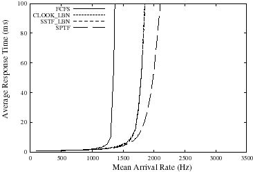
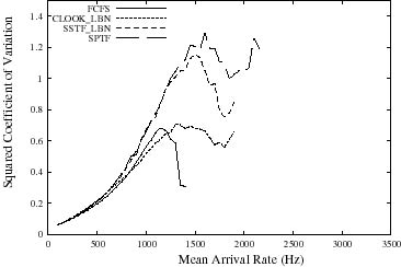
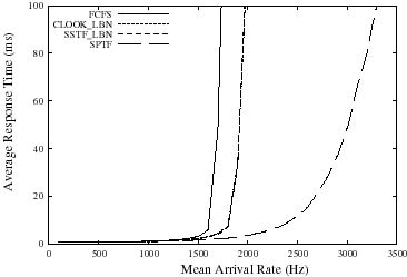
Figure 6 shows how well these algorithms work for the default MEMS-based storage device on the Random workload with a range of request arrival rates. In terms of both performance and starvation resistance, the algorithms finish in the same order as for disks: SPTF provides the best performance and CLOOK LBN provides the best starvation resistance. However, their performance relative to each other merits discussion. The difference between FCFS and the LBN-based algorithms (CLOOK LBN and SSTF LBN) is larger for MEMS-based storage devices because the seek time is a much larger component of the total service time. In particular, there is no subsequent rotational delay. Also, the average response time difference between CLOOK LBN and SSTF LBN is smaller for MEMS-based storage devices, because both algorithms reduce the X seek times into the range where X and Y seek times are comparable. Since neither addresses Y seeks, the greediness of SSTF LBN is less effective. SPTF obtains additional performance by addressing Y seeks.
 |
 |
|---|---|
| (a) Average response times | (b) Squared coefficients of variation (s2 / m2) |
Figure 6: Comparison of scheduling algorithms for the Random workload on the MEMS-based storage device. Note the scale of the X axis has increased by an order of magnitude relative to the graphs in Figure 5.
 |
 |
|---|---|
| (a) Cello average response times | (b) TPC-C average response times |
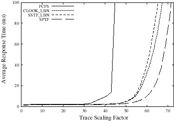
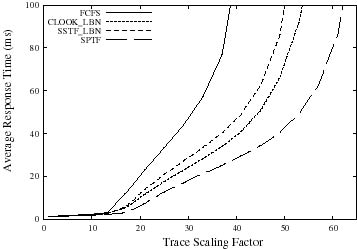
Figure 7: Comparison of scheduling algorithms for the Cello and TPC-C workloads on the MEMS-based storage device.
Figures 7(a) and 7(b) show how the scheduling algorithms perform for the Cello and TPC-C workloads, respectively. The relative performance of the algorithms on the Cello trace is similar to the Random workload. The overall average response time for Cello is dominated by the busiest one of Cello's eight disks; some of the individual disks have differently shaped curves but still exhibit the same ordering among the algorithms. One noteworthy difference between TPC-C and Cello is that SPTF outperforms the other algorithms by a much larger margin than for TPC-C at high loads. This occurs because the scaled-up version of the workload includes many concurrently-pending requests with very small LBN distances between adjacent requests. LBNbased schemes do not have enough information to choose between such requests, often causing small (but expensive) X-dimension seeks. SPTF addresses this problem and therefore performs much better.
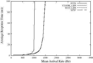
Originally, we had expected SPTF to outperform the other algorithms by a greater margin for MEMS-based storage devices. Our investigations suggest that the value of SPTF scheduling is highly dependent upon the settling time component of X dimension seeks. With large settling times, X dimension seek times dominate Y dimension seek times, making SSTF LBN match SPTF. With small settling times, Y dimension seek times are a more signifi- cant component. To illustrate this, Figure 8 compares the scheduling algorithms with the constant settling time set to zero and 0.44 ms (double the default value). As expected, SSTF LBN is very close to SPTF when the settling time is doubled. With zero settling time, SPTF outperforms the other algorithms by a large margin.
 |
 |
|---|---|
| (a) Random with zero settling time | (b) Random with double settling time |
Figure 8: Comparison of average performance of the Random workload for zero and double constant settling time on the MEMS-based storage device. These are in comparison to the default model (Random with constant settling time of 0.22 ms) shown in Figure 6(a). With no settling time, SPTF significantly outperforms CLOOK LBN and SSTF LBN. With the doubled settling time, CLOOK LBN, SSTF LBN, and SPTF are nearly identical.
Space allocation and data placement for disks continues to be a ripe topic of research. We expect the same to be true of MEMS-based storage devices. In this section, we discuss how the characteristics of MEMS-based storage positioning costs affect placement decisions for small local accesses and large sequential transfers. A bipartite layout is proposed and shown to have potential for improving performance.
As with disks, short distance seeks are faster than long distance seeks. Unlike disks, MEMS-based storage devices' spring restoring forces make the effective actuator force (and therefore sled positioning time) a function of location. Figure 9 shows the impact of spring forces for seeks inside different "subregions" of a single tip's media region. The spring forces increase with increasing sled displacement from the origin (viz., toward the outermost subregions in Figure 9), resulting in longer positioning times for short seeks. As a result, distance is not the only component to be considered when finding good placements for small, popular data items--offset relative to the center should also be considered.
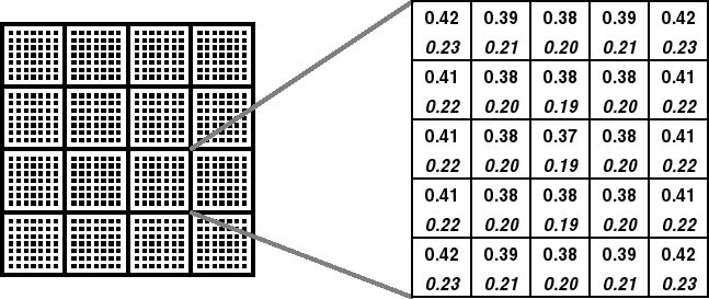
Figure 9: Difference in request service time for subregion accesses. This figure divides the region accessible by an individual probe tip into 25 subregions, each 500 × 500 bits. Each box shows the average request service time (in milliseconds) for random requests starting and ending inside that subregion. The upper numbers represent the service time when the default settling time is included in calculations; numbers in italics represent the service time for zero settling time. Note that the service time differs by 14-21% between the centermost and outermost subregions.
Streaming media transfer rates for MEMS-based storage devices and disks are similar: 17.3- 25.2 MB/s for the Atlas 10K [22]; 75.9 MB/s for MEMS-based storage devices. Positioning times, however, are an order of magnitude shorter for MEMS-based storage devices than for disks. This makes positioning time relatively insignificant for large transfers (e.g., hundreds of sectors). Figure 10 shows the request service times for a 256 KB read with respect to the X distance between the initial and final sled positions. Requests traveling 1250 cylinders (e.g., from the sled origin to maximum sled displacement) incur only a 10% penalty. This lessens the importance of ensuring locality for data that will be accessed in large, sequential chunks. In contrast, seek distance is a significant issue with disks, where long seeks more than double the total service time for 256 KB requests.
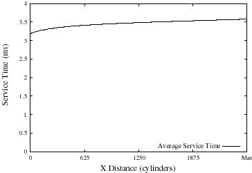
Figure 10: Large (256 KB) request service time vs. X seek distance for MEMS-based storage devices. Because the media access time is large relative to the positioning time, seeking the maximum distance in X increases the service time for large requests by only 12%.
To take advantage of the above characteristics, we propose a 25-subregion bipartite layout scheme. Small data are placed in the centermost subregions; long, sequential streaming data are placed in outer subregions. Two layouts are tested: a five-by-five grid of subregions (Figure 9) and a simple columnar division of the LBN space into 25 columns (viz., column 0 contains cylinders 0-99, column 1 contains cylinders 100-199, etc.).
We compare these layout schemes against the "organ pipe" layout [26, 32], an optimal disk-layout scheme, assuming no inter-request dependencies. In the organ pipe layout, the most frequently accessed files are placed in the centermost tracks of the disk. Files of decreasing popularity are distributed to either side of center, with the least frequently accessed files located closer to the innermost and outermost tracks. Although this scheme is optimal for disks, files must be periodically shuffled to maintain the frequency distribution. Further, the layout requires some state to be kept, indicating each file's popularity.
To evaluate these layouts, we used a workload of 10,000 whole-file read requests whose sizes are drawn from the file size distribution reported in Reference [9]. In this size distribution, 78% of files are 8 KB or smaller, 4% are larger than 64 KB, and 0.25% are larger than 1 MB. For the subregioned and columnar layouts, the large files (larger than 8 KB) were mapped to the ten leftmost and ten rightmost subregions, while the small files (8 KB or less) were mapped to the centermost subregion. To conservatively avoid second-order locality within the large or small files, we assigned a random location to each request within either the large or the small subregions. For the organ pipe layout, we used an exponential distribution to determine file popularity, which was then used to place files. Figure 11 shows that all three layout schemes achieve a 12-15% improvement in average access time over a simple random file layout. Subregioned and columnar layouts for MEMS-based storage devices match organ pipe, even with the conservative model and no need for keeping popularity data or periodically reshuffling files on the media. For the "no settling time" case, the subregioned layout provides the best performance as it addresses both X and Y.
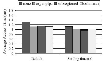
Figure 11: Comparison of layout schemes for MEMS-based storage devices. For the default device, the organ pipe, subregioned, and columnar layouts achieve a 12-15% performance improvement over a random layout. Further, for the "settling time = 0" case, the subregioned layout outperforms the others by an additional 12%. It is interesting to note that an optimal disk layout technique does not necessarily provide the best performance for MEMS-based storage.
Fault tolerance and recoverability are significant considerations for storage systems. Although MEMS-based storage devices are not yet available, MEMS components have been built and tested for many years. Their miniature size and movements will make MEMS-based storage components less fragile than their disk counterparts [17]. Still, there will likely be more defective or failed parts in MEMS-based storage because of the large number of distinct components compared to disks and the fact that bad parts cannot be replaced before or during assembly.
Although failure management for MEMS-based storage devices will be similar to failure management for conventional disks, there are several important differences. One is that individual component failures must be made less likely to render a device inoperable than in disks. Another is that MEMS-based storage devices simplify some aspects of failure management--inter-device redundancy maintenance and device restart, for example. This section discusses three aspects of failure management: internal faults, device failures, and recoverability from system crashes.
The common failure modes for disk drives include recoverable failures (for example, media defects or seek errors) and non-recoverable failures (head crashes, motor or arm actuator failure, drive electronics or channel failure). MEMS-based storage devices have similar failure modes with analogous causes. However, the ability to incorporate multiple tips into failure tolerance schemes allows MEMS-based storage devices to mask most component failures, including many that would render a disk inoperable.
Specifically, powerful error correcting codes can be computed over data striped across multiple tips. In our default model, each 512 byte logical block and its ECC are striped across 64 tips. This ECC can include both a horizontal component (across tips) and a vertical component (within a single sector). The horizontal ECC can recover from missing sectors. The vertical ECC identifies sectors that should be treated as missing--with the effect of converting some large errors into erasures, which can more easily be handled by the horizontal ECC. This single mechanism addresses most internal failures that are recoverable.
Media defects. In disk drives, unrecoverable media defects are handled by remapping logical block numbers to non-defective locations, with data often being lost when defects "grow" during operation. In MEMS-based storage, most media defects are expected to affect the data under a small number of tips (e.g., 1-4). Therefore, the horizontal ECC can usually be used to reconstruct unavailable bits. This capability is particularly important because the higher density of MEMS-based storage causes a given defect to affect more bits than it would in a disk. Tolerance of large media defects can be further extended by spreading each logical block's data and ECC among physically distant tips--graph coloring schemes excel at the types of data mappings required.
Tip failures. Failure of a conventional disk's read/write head or control logic generally renders the entire device inoperable. MEMS-based storage replicates these functions across thousands of components. With so many components, failure of one or more is not only possible, but probable-- individual probe tips can break off or "crash" into the media, and fabrication variances will produce faulty tips or faulty tip-specific logic. Most such problems can be handled using the same mechanisms that handle media failures, since failure of a tip or its associated control logic translates into unavailability of data in the corresponding tip region. The horizontal ECC can be used to reconstruct this data.
As with disk drives, spare space needs to be withheld from the fault-free mapping of data to physical locations in MEMS-base storage. This spare space is used to store data that cannot be stored at its default physical location because of media or tip failures. The parallel operation of tips within a track provides an opportunity to avoid the performance and predictability penalties normally associated with defect remapping in disk drives. Specifically, by setting aside one or more spare tips in each track, unreadable sectors can be remapped to the same sector under a spare tip. A sector remapped in this way would be accessed at exactly the same time as the original (unavailable) sector would have been. In contrast, disks "slip" LBNs over defective sectors or re-map them to spare sectors elsewhere in a cylinder or zone, changing their access times relative to their original locations.
MEMS-based storage devices are susceptible to similar non-recoverable failures as disk drives: strong external mechanical or electrostatic forces can damage the actuator comb fingers or snap off the springs, manufacturing defects can surface, or the device electronics or channel can fail. These failures should appear and be handled in the same manner as for disks. For example, appropriate mechanisms for dealing with device failures include inter-device redundancy and periodic backups.
Interestingly, MEMS-based storage's mechanical characteristics are a better match than those of disks for the common read-modify-write operations used in some fault-tolerant schemes (e.g., RAID5). Whereas conventional disks suffer a full rotation to return to the same sector, MEMS-based storage devices can quickly reverse direction, significantly reducing the read-modify-write latency (Table 2). For the Random workload, a five-disk RAID-5 system has 77% longer response times than a four-disk striping-only system (14.3 ms vs. 8.04 ms); the latency increase for MEMS-based storage devices is only 27% (1.36 ms vs. 1.07 ms).
| Atlas 10K | MEMS | |||
|---|---|---|---|---|
| # sectors | 8 | 334 | 8 | 334 |
| read | 0.14 | 6.00 | 0.13 | 2.19 |
| reposition | 5.86 | 0.00 | 0.07 | 0.07 |
| write | 0.14 | 6.00 | 0.13 | 2.19 |
| total | 6.14 | 12.00 | 0.33 | 4.45 |
Table 2: A comparison of read-modify-write times for 4 KB (8 sector) and disk track-length (334 sector) transfers. Conventional disks must wait for a complete platter rotation during read-modify-write operations, whereas MEMS-based storage devices need only perform a turnaround, a relatively inexpensive operation. This characteristic is particularly helpful for codebased redundancy schemes (for example, RAID-5) or for verify-after-write operations.
File systems and databases must maintain internal consistency among persistent objects stored on MEMS-based storage devices, just as they do for objects on disks. Although synchronous writes will still hurt performance, the low service times of MEMS-based storage devices will lessen the penalty.
Another relevant characteristic of MEMS-based storage devices is rapid device startup. Since no spindle spin-up time is required, startup is almost immediate--estimated at less than 0.5 ms. In contrast, high-end disk drives can take 15-25 seconds before spin-up and initialization is complete [22]. Further, MEMS-based storage devices do not exhibit the power surge inherent in spinning up disk drives, so power spike avoidance techniques (e.g., serializing the spin-up of multiple disk drives) are unnecessary--all devices can be started simultaneously. Combined, these effects could reduce system restart times from minutes to milliseconds.
This section discusses additional issues related to our exploration of OS management for MEMS-based storage devices.
Power conservation. Significant effort has gone into reducing a disk drive's power consumption, such as reducing active power dissipation and introducing numerous power-saving modes for use during idle times [6, 15, 16]. MEMS-based storage devices are much more energy efficient than disks in terms of operational power. Further, the physical characteristics of MEMS-based storage devices enable a simpler power management scheme: a single idle mode that stops the sled and powers down all nonessential electronics. With no rotating parts and little mass, the media sled's restart time is very small (estimated at under 0.5 ms). This relatively small penalty enables aggressive idle mode use, switching from active to idle as soon as the I/O queue is empty. Detailed energy breakdown and evaluation indicates that our default MEMS-based storage device employing this immediate-idle scheme would dissipate only 8-22% of the energy used by today's low-power disk drives [27].
Alternate seek control models. Our device model assumes that seeks are accomplished by a "slew plus settle" approach, which involves maximum acceleration for the first portion of the seek, followed by maximum deceleration to the destination point and speed, followed by a closed loop settling time. With such seek control, the slew time goes up as the square root of the distance and the settling time is constant (to the first order). The alternate seek control approach, a linear system seek, would incorporate rate proportional feedback to provide damping and a step input force to initiate movement to a desired location and velocity. Seeks based on such a control system exhibit longer seek times (including the settling times) that are much more dependent on seek distance [35]. This should not change our high-level conclusions, but will tend to increase the importance of both SPTF scheduling and subregion data layouts.
Erase cycles. Although our target MEMS-based storage device employs traditional rewriteable magnetic media, some designs utilize media that must be reset before it can be overwritten. For example, the IBM Millipede [31] uses a probe technology based on atomic force microscopes (AFMs), which stores data by melting minute pits in a thin polymer layer. A prominent characteristic of the Millipede design is a block erase cycle requiring several seconds to complete. Such block erase requirements would necessitate management schemes, like those used for Flash RAM devices [5], to hide erase cycle delays.
This paper compares and contrasts MEMS-based storage devices with disk drives and provides a foundation for focused OS management of these new devices. We describe and evaluate approaches for tuning request scheduling, data placement and failure management techniques to the physical characteristics of MEMS-based storage.
One of the general themes of our results is that OS management of MEMS-based storage devices can be similar to, and simpler than, management of disks. For example, disk scheduling algorithms can be adapted to MEMS-based storage devices in a fairly straightforward manner. Also, performance is much less dependent on such optimizations as careful data placement, which can yield order of magnitude improvements for disk-based systems [9, 19, 24]; data placement still matters, but sub-optimal solutions may not be cause for alarm. In the context of availability, internal redundancy can mask most problems, eliminating both data loss and performance loss consequences common to disk drives. Similarly, rapid restart times allow power-conservation software to rely on crude estimates of idle time.
We continue to explore the use of MEMS-based storage devices in computer systems, including their roles in the memory hierarchy [27] and in enabling new applications.
We thank Rick Carley, David Petrou, Andy Klosterman, John Wilkes, the CMU MEMS Laboratory, and the anonymous reviewers for helping us refine this paper. We thank the members and companies of the Parallel Data Consortium (including CLARiiON, EMC, HP, Hitachi, Infineon, Intel, LSI Logic, MTI, Novell, PANASAS, Procom, Quantum, Seagate, Sun, Veritas, and 3Com) for their interest, insights, and support. We also thank IBM Corporation and Intel Corporation for supporting our research efforts. John Griffin is supported in part by a National Science Foundation Graduate Fellowship.
[1] L. Richard Carley, James A. Bain, Gary K. Fedder, David W. Greve, David F. Guillou, Michael S. C. Lu, Tamal Mukherjee, Suresh Santhanam, Leon Abelmann, and Seungook Min. Single-chip computers with microelectromechanical systems-based magnetic memory. Journal of Applied Physics, 87(9):6680-6685, 1 May 2000.
[2] Center for Highly Integrated Information Processing and Storage Systems, Carnegie Mellon University. https://www.ece.cmu.edu/research/chips/.
[3] Data Storage Systems Center, Carnegie Mellon University. https://www.ece.cmu.edu/research/dssc/.
[4] Peter J. Denning. Effects of scheduling on file memory operations. AFIPS Spring Joint Computer Conference (Atlantic City, New Jersey, 18-20 April 1967), pages 9-21, April 1967.
[5] Fred Douglis, Ramon Caceres, Frans Kaashoek, Kai Li, Brian Marsh, and Joshua A. Tauber. Storage alternatives for mobile computers. Symposium on Operating Systems Design and Implementation (Monterey, CA), pages 25-39. USENIX Association, 14-17 November 1994.
[6] Fred Douglis, P. Krishnan, and Brian Marsh. Thwarting the power-hungry disk. Winter USENIX Technical Conference (San Francisco, CA), pages 292-306. USENIX Association, Berkeley, CA, 17-21 January 1994.
[7] G. K. Fedder, S. Santhanam, M. L. Reed, S. C. Eagle, D. F. Guillou, M. S.-C. Lu, and L. R. Carley. Laminated high-aspect-ratio microstructures in a conventional CMOS process. IEEE Micro Electro Mechanical Systems Workshop (San Diego, CA), pages 13-18, 11-15 February 1996.
[8] Greg Ganger and Jiri Schindler. Database of validated disk parameters for DiskSim. https://www.ece.cmu.edu/~ganger/disksim/diskspecs.html
[9] Gregory R. Ganger and M. Frans Kaashoek. Embedded inodes and explicit grouping: exploiting disk bandwidth for small files. Annual USENIX Technical Conference (Anaheim, CA), pages 1-17, January 1997.
[10] Gregory R. Ganger, Bruce L. Worthington, and Yale N. Patt. The DiskSim Simulation Environment Version 1.0 Reference Manual, CSE-TR-358-98. Department of Computer Science and Engineering, University of Michigan, February 1998.
[11] John Linwood Griffin, Steven W. Schlosser, Gregory R. Ganger, and David F. Nagle. Modeling and performance of MEMS-based storage devices. ACM SIGMETRICS 2000 (Santa Clara, CA, 17-21 June 2000). Published as Performance Evaluation Review, 28(1):56-65, June 2000.
[12] John L. Hennessy and David A. Patterson. Computer Architecture: A Quantitative Approach, 2nd ed. Morgan Kaufmann Publishers, Inc., San Francisco, CA, 1995.
[13] Hewlett-Packard Laboratories Storage Systems Program. https://www.hpl.hp.com/research/storage.html.
[14] David M. Jacobson and John Wilkes. Disk scheduling algorithms based on rotational position. HPL-CSP-91-7. Hewlett-Packard Laboratories, Palo Alto, CA, 24 February 1991, revised 1 March 1991.
[15] Kester Li, Roger Kumpf, Paul Horton, and Thomas E. Anderson. A quantitative analysis of disk drive power management in portable computers. Winter USENIX Technical Conference (San Francisco, CA), pages 279-291. USENIX Association, Berkeley, CA, 17-21 January 1994.
[16] Yung-Hsiang Lu, Tajana Simunic, and Giovanni De Micheli. Software controlled power management. 7th International Workshop on Hardware/Software Codesign (Rome, Italy), pages 157-161. ACM Press, 3{5 May 1999.
[17] Marc Madou. Fundamentals of Microfabrication. CRC Press LLC, Boca Raton, Florida, 1997.
[18] Marshall K. McKusick, William N. Joy, Samuel J. Lefler, and Robert S. Fabry. A fast file system for UNIX. ACM Transactions on Computer Systems, 2(3):181-197, August 1984.
[19] L. W. McVoy and S. R. Kleiman. Extent-like performance from a UNIX file system. Winter USENIX Technical Conference (Dallas, TX), pages 33-43, 21-25 January 1991.
[20] Microelectromechanical Systems Laboratory, Carnegie Mellon University. https://www.ece.cmu.edu/~mems/.
[21] David A. Patterson, Peter Chen, Garth Gibson, and Randy H. Katz. Introduction to redundant arrays of inexpensive disks (RAID). IEEE Spring COMPCON (San Francisco, CA), pages 112-117, March 1989.
[22] Quantum Corporation. Quantum Atlas 10K 9.1/18.2/36.4 GB Ultra 160/m SCSI Hard Disk Drive Product Manual, Publication number 81-119313-05, August 6, 1999.
[23] Erik Riedel, Christos Faloutsos, Gregory R. Ganger, and David F. Nagle. Data mining on an OLTP system (nearly) for free. ACM SIGMOD Conference 2000 (Dallas, TX), pages 13-21, 14-19 May 2000.
[24] Mendel Rosenblum and John K. Ousterhout. The design and implementation of a log-structured file system. ACM Transactions on Computer Systems, 10(1):26-52, February 1992.
[25] Chris Ruemmler and John Wilkes. UNIX disk access patterns. Winter USENIX Technical Conference (San Diego, CA), pages 405-420, 25-29 January 1993.
[26] Chris Ruemmler and John Wilkes. Disk Shuffling. Technical report HPL-91-156. Hewlett-Packard Company, Palo Alto, CA, October 1991.
[27] Steven W. Schlosser, John Linwood Griffin, David F. Nagle, and Gregory R. Ganger. Designing computer systems with MEMS-based storage. Ninth International Conference on Architectural Support for Programming Languages and Operating Systems (Boston, Massachusetts), 13-15 November 2000. To appear.
[28] P. H. Seaman, R. A. Lind, and T. L. Wilson. On teleprocessing system design, part IV: an analysis of auxiliarystorage activity. IBM Systems Journal, 5(3):158-170, 1966.
[29] Margo Seltzer, Peter Chen, and John Ousterhout. Disk scheduling revisited. Winter USENIX Technical Conference (Washington, DC), pages 313-323, 22-26 January 1990.
[30] T. J. Teorey and T. B. Pinkerton. A comparative analysis of disk scheduling policies. Communications of the ACM, 15(3):177-184, March 1972.
[31] P. Vettiger, M. Despont, U. Drechsler, U. Durig, W. Haberle, M. I. Lutwyche, H. E. Rothuizen, R. Stutz, R. Widmer, and G. K. Binnig. The "Millipede" - more than one thousand tips for future AFM data storage. IBM Journal of Research and Development, 44(3):323-340, 2000.
[32] Paul Vongsathorn and Scott D. Carson. A system for adaptive disk rearrangement. Software - Practice and Experience, 20(3):225-242, March 1990.
[33] Kensall D. Wise. Special issue on integrated sensors, microactuators, and microsystems (MEMS). Proceedings of the IEEE, 86(8):1531-1787, August 1998.
[34] Bruce L. Worthington, Gregory R. Ganger, and Yale N. Patt. Scheduling for modern disk drives and non-random workloads. CSE-TR-194-94. Department of Computer Science and Engineering, University of Michigan, March 1994.
[35] Pu Yang. Modeling probe-based data storage devices. Technical report. Department of Computer Science, University of California Santa Cruz, June 2000. Master's thesis.
|
This paper was originally published in the
Proceedings of the 4th USENIX OSDI Symposium,
October 23-25, 2000, San Diego, California, USA.
Last changed: 16 Jan. 2002 ml |
|