NSDI '06 Paper
[NSDI '06 Technical Program]
OCALA: An Architecture for Supporting Legacy Applications over Overlays
| Dilip Joseph* |
Jayanth Kannan* |
Ayumu Kubota+ |
Karthik Lakshminarayanan* |
Ion Stoica* |
Klaus Wehrle^ |
| *University of California at Berkeley |
+KDDI Labs |
^RWTH Aachen University |
|
Abstract:
In order for overlays and new network architectures to gain real user
acceptance, users should be able to leverage overlay functionality
without any modifications to their applications and operating
systems.
We present our design, implementation, and experience
with OCALA, an overlay convergence architecture that achieves this
goal. OCALA interposes an overlay convergence layer below the
transport layer. This layer is composed of an overlay independent
sub-layer that interfaces with legacy applications, and an overlay
dependent sub-layer that delivers packets to the overlay. Unlike
previous efforts, OCALA enables: (a) simultaneous access to
multiple overlays (b) communication between hosts in different
overlays (c) communication between overlay hosts and legacy hosts (d)
extensibility, allowing researchers to incorporate their overlays into
OCALA.
We currently support five overlays, i3 [32],
RON [1], HIP [19], DOA [39] and OverDoSe [31]
on Linux, Windows XP/2000 and Mac OS X.
We (and a few other research groups and end-users) have used
OCALA for over a year with many legacy applications ranging from web
browsers to remote desktop applications.
1 Introduction
Over the past two decades, researchers have proposed a plethora of
solutions to extend the Internet's functionality, and to improve its
resilience and security. After sustained efforts to add new functions
such as mobility [25] and multicast [5]
to IP, researchers have recently turned their attention to developing
new network architectures (e.g., [1, 32, 35, 3, 19, 4, 29]) and using overlays to address the Internet's
limitations.1 This trend has
been fueled by the difficulty of changing IP, on one hand, and by the
advent of the PlanetLab[26] testbed and the recent NSF
GENI [23] initiative—which promises to create a worldwide
testbed for evaluating new network architectures—on the other hand.
In order to evaluate the feasibility of these proposals and to
ultimately bring them closer to reality, it is important to experiment
with real users running real applications. Ideally, users should be
able to opt into new experimental architectures without any changes to
their legacy applications. (We use the term legacy applications to
refer to existing applications like web browsers that assume IP
semantics.) Supporting legacy applications on new network
architectures is inherently a difficult task: legacy applications
assume traditional semantics of IP addresses and DNS names, while a
new network architecture may offer a substantially different
interface. Existing solutions are in general tailored to a particular
network architecture [1, 43, 19, 34], leading to
duplication of effort across different implementations.
In this paper, we describe the design and implementation of our
solution, OCALA (Overlay Convergence Architecture for Legacy
Applications), that enables legacy applications to take advantage of
the functionality provided by new network architectures. OCALA differs
from existing solutions in that it enables (1) applications running on
the same machine to access different overlays simultaneously, (2)
stitching of multiple overlays so that users residing in different
overlays can communicate with each other, (3) hosts to communicate
through an overlay even if the other end-point understands only IP,
and (4) extensibility so that a new overlay can be incorporated into
OCALA with minimal effort.
In a nutshell, OCALA re-factors the protocol stack by imposing an Overlay Convergence (OC) layer. The OC layer is positioned below the
transport layer in the IP stack. It is decomposed into the
overlay-independent (OC-I) sub-layer, which interacts with the legacy
applications by presenting an IP-like interface, and the
overlay-dependent (OC-D) sub-layer, which tunnels the traffic of
applications over overlays.
The main contributions of this paper are an overlay agnostic
architecture for supporting legacy applications and an extensible
implementation of this architecture as a proxy. Our implementation of
OCALA as a proxy requires no changes to applications or operating
systems.
In realizing our design, we borrow many techniques and protocols from
the literature, such as address virtualization [12, 34, 36, 42, 43, 19], DNS capture and
rewriting [42, 22, 9, 28], and
SSL [10]. We have implemented the OC-D sub-layer for i3 and RON.
In addition, OC-D modules for HIP [14], DOA [39] and
OverDoSe [31] have been implemented by other research groups.
To illustrate the
utility of OCALA, we have provided services such as
intrusion-detection, secure wireless access, secure Intranet access,
and Network Address Translation (NAT) box traversal, to legacy
applications.
OCALA does not come without limitations. The fact that OCALA is
positioned below the transport layer makes it hard, if not impossible,
for legacy applications to take advantage of network architectures
that provide transport or application layer functionalities, such as
multi-path congestion control and data storage [17].
2 Related Work
Supporting legacy applications over non-IP or IP-modified
communication infrastructures has been addressed in many contexts.
Examples include overlay networks and new network architectures (e.g., RON [1], i3 [32], HIP [19],
DOA [39], WRAP [2], end-host support for
mobility [34, 36, 42]), and mechanisms that
enable end-hosts to use overlays without participating in
them [21].
In contrast to these overlay-specific efforts, OCALA enables a user to
simultaneously access different overlays and to communicate with hosts
residing in overlays the user is not directly connected to.
A recent system, Oasis [18], enables legacy applications to
route traffic through different overlays, and has a design similar to
that of OCALA. However, Oasis's current implementation supports only
overlays that are IP-addressable, and does not allow stitching
together multiple overlays. In contrast, OCALA supports overlays that
address hosts using a variety of identifiers and naming schemes (e.g., i3, DOA), and allows hosts on different overlays to communicate with
each other. Oasis optimizes application performance by automatically
selecting the “best” overlay. Furthermore, Oasis supports sandboxed
code execution, a direct result of its Java-based implementation. The
current implementation of OCALA does not support any of these
features.
Our goal of stitching together multiple network architectures
resembles the goal of AVES [22], TRIAD [3],
UIP [7], IPNL [8],
Plutarch [4], and IPv4/IPv6 transition schemes like
[11]. In contrast to these proposals which provide universal
connectivity, OCALA's focus is on exposing to users,
functions that new architectures provide, both in isolation
and when stitched together.
Layering is a widely-used principle in networking. Many architectures
(e.g., HIP [19], WRAP [2]) hide the details of underlying
layers by interposing a shim layer between the transport and network
layers. More recently, Henderson generalized the HIP setup protocol
to support other architectures that decouple location and identity of
hosts [13]. OCALA's OC layer is similar to such a shim
layer. OCALA is different from other architectures in that it
explicitly splits the OC layer into an overlay independent sub-layer
and an overlay dependent sub-layer, which respectively act as
traditional network and link layers. This division enables OCALA to
provide simultaneous access to and inter-operability across different
network architectures.
For implementing OCALA, we rely on techniques and protocols
previously proposed in different contexts.
Intercepting DNS requests for interposing proxies on the data path has
been used in AVES [22], Coral [9], and for improving
web browsing performance over wireless
networks [28]. Local-scope addresses have been utilized
in the context of supporting mobility [34, 36, 42, 19], redirection [12], process
migration [34, 33] and server
availability [33]. Our address-negotiation protocol is
similar to that in Yalagandula et. al. [42], while
the OC-I sub-layer's security protocol is a generalization of SSL [10].
3 Design Overview
We focus on network architectures and overlays that offer a service
model of end-to-end packet delivery similar to IP's, as opposed to
those that provide transport- or application-layer functions, such as
data storage (e.g., Oceanstore [17]). Some examples are
overlays that improve Internet's resilience and performance (e.g., RON [1], Detour [29],
OverQoS [35]), overlays that provide new functions (e.g., mobility [43, 42]), overlays that bridge multiple address
spaces [2, 22], as well as recent architectures such
as i3 [32], HIP [19], and DOA [39]. Although not all
architectures are realized as overlays, for convenience, in the
remainder of this paper, we will use the term overlay to also
refer to
network architectures that are implemented as overlays.
Each end-host E in an overlay has an overlay-specific identifier
(ID), which is used by other end-hosts to contact E through the
overlay. While in the simplest case an overlay ID can be the host's
IP address (e.g., RON), many overlays use other forms of identifiers
(e.g., i3 and DOA use flat IDs, HIP uses hashes of public keys). Since
overlay IDs may not be human-readable, end-hosts may also be assigned
human-readable names for convenience.
3.1 Goals
Our design is centered around four main goals:
-
Transparency: Legacy applications should not break despite
the fact that their traffic is relayed over an overlay instead of over
IP.
- Inter-operability: Hosts in different overlays should be
able to communicate with one another, and further, hosts that do not participate in any
overlay should also be accessible through overlays.
- Expose overlay functionality: Users should have control in
choosing the overlay used to send their traffic, and should be able to
leverage the overlay functions despite using overlay-unaware (legacy)
applications.
- Factor out common functions: Instead of relying on the
security provided by overlays, the architecture should provide basic
security features such as host authentication and encryption.
Figure 1: The overlay convergence (OC) layer.
3.2 Overlay Convergence Layer
OCALA interposes a layer, called the overlay
convergence (OC) layer, between the transport and the network
layers (see Figure 1). The OC layer replaces the IP
layer in the Internet's stack, and consists of two sub-layers: an
overlay independent (OC-I) sub-layer, and an overlay dependent (OC-D)
sub-layer.
The main functions of the OC-I sub-layer are to present a consistent
IP-like interface to legacy applications and to multiplex/demultiplex
traffic between applications and various overlays.
In addition, the OC-I sub-layer provides common functions, such as
authentication and encryption, that are useful across overlays.
The OC-D sub-layer consists of modules for various overlays, which are
responsible for setting up overlay-specific state and for
sending/receiving packets to/from the particular overlay. For example,
the i3 OC-D module maintains private triggers at both
end-points, while the OverQoS module performs resource reservation.
Note that IP can be viewed as a “default” overlay module.
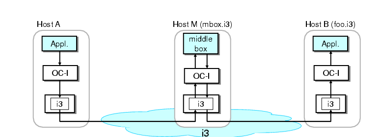
Figure 2: Three applications on host (A) which establish connections
via IP and two overlays: RON and i3.
Figure 2 shows an example in which three
applications on host A open connections over IP and two overlays: a
web browser (Firefox) uses IP to connect to a CNN server, a chat
client (IRC) uses i3 to preserve its anonymity, and ssh uses
RON for improved resilience. The design also enables hosts in
different overlays to communicate with each
other. Figure 3 shows how two hosts on different
overlays can communicate using a gateway host (B) that is
connected to both overlays.
We refer to the end-to-end communication channel between two end-hosts
at the OC-I sub-layer as a path, and to the communication channel
between two end-hosts at the OC-D sub-layer as a tunnel. In
Figure 3 the path between the two
end-hosts is (A, B, C), and consists of two tunnels, (A, B) and (B,
C).
3.3 Layering in OCALA: Discussion
The services implemented by the OC-I and OC-D sub-layers on the data
plane are analogous to the services provided by the network and
data-link layers in the OSI protocol stack respectively. Like the
data-link layer which provides communication between any two nodes in
the same link layer domain, OC-D provides communication between any
two nodes in the same overlay. Similarly, like the network layer
which provides communication across different link layer domains, the
OC-I sub-layer provides communication across different overlays.
However, OCALA does not enforce strict layering within its sub-layers.
Unlike traditional layering, where a layer uses only the services
provided by the layer below, OCALA allows legacy applications to
access the services provided by the OC-D sub-layer, by passing
overlay-specific names or IDs to OC-D through the OC-I sub-layer.
These names are resolved at the OC-D sub-layer, and their semantics is
opaque to the OC-I sub-layer. This allows us to achieve the main goal
of OCALA—enable legacy applications to take advantage of the
functions provided by overlays—while keeping the OC-I sub-layer
agnostic of the overlays.
4 Detailed Architecture
We present a goal-driven description of OCALA, by showing how our
design achieves the four goals we laid out in
� 3.1.
Achieving these design goals is challenging as they have conflicting
requirements. For instance, on one hand, we want to expose the rich
functionality provided by overlays to users, while on the other, we
have to preserve the narrow IP interface exposed to the legacy
applications. Our design aims to find a sweet spot in achieving
these opposing goals.
Figure 3: Bridging multiple overlays.
4.1 Goal 1: Achieving Transparency
Our main goal is to ensure that legacy applications are oblivious to
the existence of overlays. Ideally, applications should work without
any changes or re-configuration when IP is replaced by the OC layer.
Our design is fundamentally constrained by how a legacy application
interacts with the external world. Most legacy applications make a
DNS request, and then send/receive IP packets to/from the IP address
returned in the DNS reply. Thus, legacy applications identify Internet
hosts using names and IP addresses, where names are resolved using DNS
to IP addresses.
We now describe and justify the following design decisions regarding
names and IP addresses exposed to the legacy application:
- Overlay hosts are identified primarily using names. These names
are resolved using overlay-specific resolution protocols. Each overlay
can implement its resolution protocol, which may differ from a DNS
lookup.
- The IP address returned to the application by the resolution
protocol has only local meaning. This address serves as an OC-I
handle to retrieve state corresponding to the remote host. Similarly,
a tunnel descriptor is used by the OC-D sub-layer to maintain
hop-by-hop state, and a path descriptor is used at the OC-I sub-layer
to maintain end-to-end state.
4.1.1 Overlay Names
Users can exercise control over the overlay used for delivering their
traffic by using: (a) fields in the IP headers, e.g., IP addresses, port
numbers, or (b) DNS-like names.
In the first approach, a user can specify rules on how packets should
be processed using fields in the IP header. For example, the user can
specify that packets sent to address 64.236.24.4 and port 80 should be forwarded through RON, while packets sent to 207.188.7.x should be forwarded through OverQoS.
In the second approach, users can encode the overlay to be used
in the DNS names. We refer to the
unique name associated with each overlay host as its overlay
name. An overlay name is of the form foo.ov, where ov
specifies the overlay, and foo is a name unique to that
overlay. On receiving a DNS request for an overlay name,
the OC layer sets up state which allows it to intercept
and forward all the subsequent packets from the application to host
foo.ov through overlay ov.
The main advantage in relying solely on the information in the IP
headers is that it works with all Internet applications, since
at the very least, an application sends and receives IP packets. On
the other hand, using overlay names has several advantages. First,
overlay names can be used to identify hosts (for example, NATed hosts)
without routable IP addresses. This property is fundamental to
overlays that bridge multiple address spaces [3, 22].
Second, names are human-readable and hence easier to use. Third, the
user does not need to know the IP address of the destination in advance, which is not feasible in some cases. Indeed, when an overlay
provides support for content replication, the IP address of the server
that ultimately serves the content may not be known to the users.
Our implementation chooses DNS-like names as the primary method for
overlay selection. For supporting applications that do not make DNS
requests, we also support the use of IP header fields for overlay
selection.
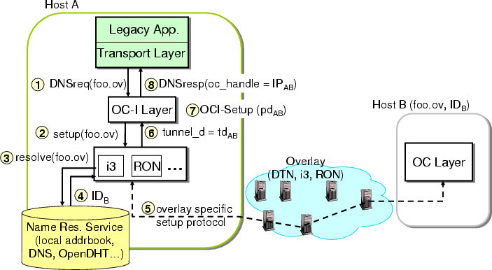
Figure 4: Path setup protocol.
4.1.2 Overlay-specific Resolution
Our second design decision is to resolve overlay names using
overlay-specific mechanisms. A name of the form foo.ov, is
resolved by the OC-D module for overlay ov. This design choice
has two main advantages over DNS-based resolution. First, this allows
multiple namespaces to co-exist with each other and with the DNS
namespace, thus enabling a fully extensible namespace. Each overlay
is allowed to implement its name allocation and resolution, without
requiring a global infrastructure. Second, this allows OCALA to
support network architectures that do not assume global IP address
allocation. Examples include MetaNet [41] and
IPNL [8] wherein names are the only way to refer to
hosts. Other examples include architectures that leverage name
resolution to implement different functions (e.g., DoA [39]).
In the remainder of the section, we describe how the control plane and
data plane operations of OCALA transparently set up an end-to-end path
and tunnel the legacy applications' data across the overlay.
4.1.3 Control Plane: End-to-End Path Setup
A new connection setup is triggered by the receipt of a DNS request
for a previously unseen overlay destination or the receipt of the
first data packet of a connection configured to use a particular
overlay. The final result of these operations is establishing an
end-to-end path at the OC-I sub-layer and setting up the state
required to handle the application's traffic. While a path could
consist of several tunnels at the OC-D sub-layer, in this
section we consider a single-tunnel path. We generalize the
description to multi-tunnel paths in
� 4.2.
Consider a legacy application on host A that wants to communicate with
a remote legacy application at host B, called foo.ov (see
Figure 4). The application first issues a DNS
request
for foo.ov, which is intercepted by the OC-I sub-layer. On
receiving such a request, the OC-I sub-layer associates a globally
unique path descriptor, pdAB, and remembers the mapping
between the name and the descriptor (foo.ov→pdAB) in
order to service future requests for foo.ov. We minimize
collisions by randomly choosing the path descriptor from a 128-bit
number space.
The OC-I sub-layer then invokes the corresponding module in the OC-D
sub-layer to setup a tunnel to foo.ov through overlay ov.
In turn, the OC-D sub-layer invokes a resolution service to obtain the
overlay ID (IDB) of foo.ov. Examples of resolution services
are DNS (used in RON), OpenDHT [16] (used in DOA), and
implicit name-to-identifier hashing (used in i3). After the OC-D
sub-layer resolves the name, it instantiates the necessary state for
communicating with foo.ov, and returns a pointer to this state,
the tunnel descriptor, tdAB, to OC-I. For example, in i3,
the setup phase involves negotiating a pair of private triggers with
the remote end-host, and instantiating the mapping state between foo.ov and the private trigger IDs.
On receiving the tunnel descriptor tdAB from OC-D, the OC-I
sub-layer at A then performs an OC-I sub-layer setup with its peer
sub-layer at B. The OC-I sub-layer at host B allocates a
descriptor for the tunnel at the OC-D sub-layer (tdBA), and an OC
handle (IPBA). When OC-I sub-layer setup is completed, the OC-I
sub-layer at host A stores the mapping
(pdAB→tdAB), and returns an OC handle
(oc_handle) to the application in the form of a local-scope IP
address, IPAB. To maintain compatibility with IP, IPAB
belongs to an unallocated address space (e.g., 1.x.x.x [15]). Figure 5 shows the
state instantiated at hosts A and B during the setup protocol.
The setup operations when the first data packet of a
connection is intercepted are similar; we do not describe it here.
4.1.4 Data Plane: Packet Forwarding
The application at host A addresses packets destined to foo.ov to IPAB, the OC handle returned by the OC-I sub-layer (see
Figure 5). The OC-I sub-layer retrieves the
state associated with this handle, and appends the path descriptor,
pdAB, to the packet, before handing it off to the OC-D sub-layer to be
sent over tunnel tdAB. The OC-D sub-layer, using its tunnel
state, sends the packets to foo.ov using the overlay ID,
IDB. At the destination, the packet is handed to the OC-I
sub-layer, which uses the path descriptor in the header to demultiplex
the packet. Before sending the packet to the application, the OC-I
sub-layer rewrites the source address to IPBA, the
OC handle associated with the A to B path at B. The
destination address is rewritten to the local IP address
at B.
As evident from this description, the constraint imposed by supporting
unmodified applications leaves us with little choice but to
overload the semantics of application-level names and IP addresses.
We discuss the limitations of overloading names and addresses on
transparency in � 4.5.
Figure 5: Forwarding a data packet from host A (with IP address
IPA) to B (with IP address IPB). The mappings used to
modify the packet are in bold.
4.2 Goal 2: Bridging Multiple Overlays
When multiple overlays are deployed, a potential undesirable
side-effect is that hosts in different overlays may not be able to
reach one another. For example, i3 allows NATed hosts to act as
servers, but such servers will be unreachable through RON. Even in
the Internet, hosts in different IP address spaces cannot communicate
with one another [22]. Moreover, it is likely that some of the
Internet hosts will not participate in overlays.
Our architecture addresses these problems by allowing remote
resolution of names, a mechanism borrowed from other
architectural proposals such as DOA [39]. When a host belonging
to overlay ov1 resolves an overlay name foo.ov2, the OC-I
sub-layer resolves the name by forwarding the request to a gateway which participates in
the overlay ov2.
We provide interoperability between overlay and legacy hosts by
designing special OC-D modules that send and receive IP traffic to
and from legacy hosts.
When performing remote resolution, path descriptors are used as state
handles across intermediate hops (such as gateways). The tunnel
descriptor is a handle passed between the OC-I and the OC-D sub-layers
at the same host; the path descriptor is used as a handle
between the OC-I sub-layers at different hosts. Thus,
intermediate hops can use the path descriptor to retrieve state
required to relay the packet further. Further, decoupling path and
tunnel descriptors allows different paths to share the same tunnel.
For example, paths (A,B,C) and (A,B,D) can share the tunnel
(A,B).
We now describe our mechanisms to bridge different overlays in more
detail.
4.2.1 Overlay Gateways
Consider a host A that uses the i3 overlay wishing to contact a
host C in the RON overlay (See Figure 3). To enable
this communication, we deploy a host (gateway) B that resides on both
i3 and RON, and runs the OC-D modules for both overlays. Host A then sets up a two-hop path to C by using the gateway as an
intermediate hop.
For a multi-hop path, the setup protocol creates tunnels between
consecutive hops and sets up the routing state at the OC-I sub-layer
of the intermediate hop to create an end to end path. We now give the
details of the protocol.
Assume that the overlay name of host C is foo.ron. Configuration
files at host A (described in � 4.3) indicate
that connections to foo.ron should go through a gateway B in i3
with the name bar.i3. To communicate with host C, an application
at host A issues a DNS request for foo.ron. The OC-I sub-layer,
upon intercepting this request, instructs the i3 OC-D module to set
up a tunnel to bar.i3. This operation is identical to the tunnel
setup in � 4.1.3. Once this tunnel is setup, the
OC-I at A asks its peer at B to set up the rest of the path to the
destination C recursively.
At the end of the setup protocol, an end-to-end path is established
from A to C with the unique path descriptor pd. A common path
descriptor helps identify a path so that any path breakages can be
dynamically detected and quickly repaired. Our gateway, as in the
case of a NAT, maintains per-path state.
Figure 6: (a) An overlay client connecting to a legacy
server. (b) A legacy client connecting to an overlay server.
4.2.2 Legacy Gateways
Legacy gateways are similar to overlay gateways except that one of the
tunnels is over IP to a legacy host that does not participate in any
overlay natively and does not run the OC-I sub-layer. Thus, overlay
functionality, such as improved routing, will be available only on the
tunnel established over the overlay (between an overlay host and the
gateway). There are two types of legacy gateways:
Legacy server gateway. The legacy server (LS) gateway allows an
overlay-enabled client to contact a legacy server (see
Figure 6(a)). Functionally, the LS gateway
runs an OC-I sub-layer over an OC-D module (say i3) and a special OC-D
module called LegacyServerIP (or LSIP). The setup protocol is
similar to that for an overlay gateway. Consider a overlay host
connecting to cnn.com through the LS gateway.
The OC-I sub-layer at the LS gateway forwards such setup requests to the
LSIP module. The LSIP module now behaves like a NAT box with respect
to the server. It first resolves the name cnn.com using DNS
and allocates a local port for this tunnel. Packets sent to the server
are rewritten by changing the source address to that of the LS
gateway, and altering the source port to be the allocated local port.
The local port is then used to multiplex incoming packets, which are
then sent to the OC-I sub-layer with the appropriate handle.
Legacy client gateway. The legacy client (LC) gateway enables
overlay servers to offer their services to legacy clients; legacy
clients are not overlay enabled, nor do they run the OC-I sub-layer
(see Figure 6(b)). The LC gateway runs the
OC-I sub-layer over an OC-D module (say i3) and a special OC-D module
called LegacyClientIP (or LCIP). In addition, the client is
configured to use the LC gateway as its DNS server. The LCIP module
intercepts DNS queries from the client, and dispatches them to the
OC-I sub-layer which initiates a tunnel over the overlay. The LCIP
module then sends a DNS reply with an Internet routable address
to the client, captures packets sent by the legacy client to that
address, and sends them over the overlay. Any client can now contact
the machine foo.i3 from any machine provided that its DNS server
is set to the address of the LC gateway. The design of our LC gateway
is similar to that of AVES [22]. The fact that the addresses
returned by the gateway should be routable considerably limits the
number of clients that can connect
simultaneously [22]. HTTP traffic does not suffer from
this limitation since gateways can use DNS names in the HTTP requests
for demultiplexing.
4.3 Goal 3: Exposing Overlay Functionality
Different new architectures and overlays provide different functions.
Users should be able to choose the overlay best suited for a
particular application.
The overlay selected might allow further customization of the
functions it offers. For example, RON allows users to choose the
metric based on which the paths are optimized, OverQoS allows users to
specify QoS parameters, and architectures like i3 and DOA allow users
to explicitly interpose middleboxes on the path. For flexibility,
users should be able to customize their preferences for each tunnel
along a path. Preferences include both overlay-specific (e.g., use
latency optimized paths for RON) and overlay-independent options (e.g., identity of gateways, end-to-end authentication).
Given the limited options available to a legacy application for
communicating its preferences to the OC layer, our initial design was
to encode the user preferences in the DNS name. For example, a DNS
name foo.delay50ms.overqos was used to identify a connection to
the host with name foo using a path of less than 50 ms delay in
OverQoS. However, overloading DNS names to include preferences had
multiple disadvantages, from highly restrictive syntax to being plain
cumbersome to utilize. Although this approach is implemented in
OCALA, we do not use it.
        <PathInfo>
            <Match urlPattern="*.ron" />
            <Match protocol="tcp" dstPort="22" />
            <Hop
                overlayId="PLron"
                routingMetric="minLatency"
            />
        </PathInfo>
Figure 7: Configuration snippet indicating that ssh traffic or connections to all DNS names ending in .ron should go over an instance of RON running on PlanetLab, using the minimum latency metric.
Instead, we opted for expressing user preferences using XML
configuration files. On receiving a setup request for an overlay
name, the OC-D sub-layer reads the preferences associated with the
name (if any) from the configuration file, before proceeding with the
setup operation. A snippet from a configuration file is shown in
Figure 7. Though directly manipulating the
configuration files offers great flexibility, we expect
users to rely on our graphical user interface described in
� 7.
4.3.1 Support For Middleboxes
OCALA also allows users to customize their data path by redirecting
traffic through specific middleboxes using the configuration files.
Several new network architectures [32, 39] provide support for
such middleboxes, by allowing both the sender and the receiver to explicitly insert middleboxes on the data path.
OCALA's support for middleboxes is similar to that for gateways.
Consider the case of a sender-imposed middlebox where a host A
wishes to contact a host B through a middlebox M (see Figure
8). The only difference from the operation of a
gateway is that the middlebox module running at M should be allowed
to perform arbitrary transformations on the data sent by one end-point
before forwarding it to the other. In OCALA, the middlebox module
implements a single function call that is used by the OC-I sub-layer
to pass packets to it. A configuration file at M specifies the
middlebox operations to be applied to connections traversing the
middlebox. The protocol for receiver-imposed middleboxes is similar.
Figure 8: Interfacing a middlebox.
4.4 Goal 4: Factoring Out Common Functions
A second-order goal aimed at reducing the effort of overlay
developers, is to leverage the OC-I sub-layer to implement generic
functions, such as security and data compression, that can be used by
different overlays.
Security and authentication of data connections are important
requirements for many overlays, especially in cases where flat names
are employed. OCALA incorporates basic security mechanisms at the
OC-I sub-layer. In particular, the OC-I sub-layer offers encryption and authentication, both of which operate agnostic
of the overlay used for the traffic. The OC-I sub-layer's
authentication mechanism is based on human-readable names and relies
on the existence of a certification and name-allocation authority from
which users can obtain certificates associating their overlay name to
their public key.2
OCALA's protocol for securely communicating with a host known by its
name alone is very similar to the Secure Sockets Layer protocol
(SSL) [10] which relies on certificate authorities like
VeriSign.
We designed our own custom protocol rather than reusing SSL since in
general middleboxes need to operate on unencrypted data, which is not
possible under the existing end-to-end model of SSL.
4.5 Limitations
The primary goal of our design is to achieve transparency for legacy
applications while providing complete access to overlay functions. We
review how well our design meets this goal.
4.5.1 Access to Overlay Functions
While the OC layer enables legacy applications to take advantage of
most overlay functions such as mobility, anycast, QoS, route
optimizations and middleboxes, there are two important limitations.
First, the fact that OCALA is positioned below the transport layer
makes it hard, if not impossible, for legacy applications to take
advantage of overlay networks that provide transport- or
application-layer functionalities (e.g., multi-path congestion control,
or data storage [17]). Second, the current
instantiations of OCALA support only unicast legacy
applications; it provides no support for legacy applications using IP
multicast; we are currently designing a multicast abstraction at the
OC-I sub-layer.
4.5.2 Transparency
The OC-I sub-layer overloads IP addresses in ways that might break
assumptions made by some applications. In contrast to usual IP
semantics, the scope of addresses returned by the OC-I sub-layer to
applications is local. Firstly, the use of local scope addresses
implies that addresses returned to legacy applications will not be
valid at other hosts. In our experience, this does not break several
common applications like ssh, Internet Explorer, remote desktop, and
ftp servers. However, peer-to-peer applications and SIP may not work
under OCALA (unless all hosts run OCALA). Secondly, applications like
ftp that encode addresses in data packets will potentially not
work since the OC-I sub-layer performs IP header rewriting before
delivering packets to the application. Our implementation avoids
address rewriting to some extent by negotiating the local addresses at
the OC-I sub-layer, a technique borrowed from [42].
However, for legacy gateways, address rewriting cannot be avoided.
Local-scope addresses have been used before in several contexts and
their limitations and workarounds are well-known [42]. In
supporting overlays where hosts may not have routable IP
addresses, we are left with little choice but to work around the
limitations of local-scope addresses using mechanisms like address
negotiation.
5 The Overlay Dependent Layer
The overlay dependent sub-layer implements the functions specific to
an overlay. We first present the interface that is exported by an
OC-D module to the OC-I sub-layer. We then describe the working of
the OC-D modules for two overlays, i3 [32] and
RON [1], which we developed in-house. This description
serves not only as a validation of our architecture but also as a
blueprint for implementing OC-D modules for other overlays.
5.1 OC-D Module API
Table 1 shows the basic API functions that every OC-D
module needs to implement and expose to the OC-I sub-layer. For
simplicity of exposition, we omit error-related functions here.
| Function calls: OC-I → OC-D |
| setup(name,pref, path_d) |
setup path to host name using preferences pref |
| close(tunnel_d) |
close tunnel |
| send(tunnel_d, IP_pkt) |
send IP packet via tunnel |
| Callbacks: OC-D → OC-I |
| setup_done(path_d, tunnel_d) |
callback invoked when tunnel (tunnel_d) was established |
| recv(path_d, IP_pkt) |
receive IP packet from tunnel |
Table 1: OC-D Module API.
The basic API consists of three functions and two callbacks. The setup function sets up a tunnel between the local host and a remote
host according to the user's preferences. The user preferences pref and the overlay name of the remote host name are passed in
the setup call.
The path_d field represents the path descriptor at the OC-I
sub-layer and is used by the OC-D sub-layer in the setup_done
callback. Once the OC-D sub-layer creates the tunnel it returns the
tunnel descriptor (tunnel_d) to the OC-I sub-layer using callback
setup_done. The close function call is invoked by the
OC-I sub-layer to close the specified tunnel. This function is usually
called when a path's state at the OC-I sub-layer expires. We discuss
the timeout values for this state in the implementation
section (� 7.1).
The send function call, invoked by the OC-I sub-layer, includes a
handle to the OC-D's state for that tunnel (i.e. the tunnel
descriptor) and the packet itself. The recv call, is invoked by
an OC-D module to the OC-I sub-layer, upon receiving a packet from the
overlay.
5.2 The RON Module
RON [1] aims to improve the resilience of the Internet by using alternate
routes in the overlay. RON offers an interface
similar to IP, and not surprisingly, it requires very little effort to
implement the OC-D module for RON. RON uses IP addresses and DNS
names as overlay IDs and overlay names, respectively.
When the OC-I sub-layer asks the RON module to setup a connection to a
RON host (identified by a name such as foo.com.ron), this name
is resolved using the DNS infrastructure to obtain an IP address. The
RON module then sets up state associating the preferences and the
destination IP address with the tunnel and passes its handle to the
OC-I sub-layer. Data plane operations involve simple encapsulation and
decapsulation.
5.3 i3 Module
i3 [32] is a network architecture that uses a rendezvous-based
communication abstraction to support services like mobility,
multicast, anycast and service composition. We now describe how the
i3 module works when host A contacts host B over i3.
On receiving the setup request for B.i3 from the OC-I
sub-layer, the i3 OC-D module at A first resolves the name to a
256-bit i3 identifier by using implicit mapping: the identifier of
a host is derived by simply hashing its name. The identifier obtained
by hashing B.i3 corresponds to B's public trigger identifier
idB. Thus, i3 does not require any resolution infrastructure.
After the name is resolved, the i3 module at A initiates private
trigger negotiation by contacting host B through its public trigger
[idB|B]. Both hosts exchange a pair of private triggers
[idAB|A] and [idBA|B], respectively, after which they
communicate exclusively through these triggers: host A sends packets
to host B using ID idBA, and host B sends packets to A
using ID idAB. Once the control protocol sets up the required
state, the i3 module sends packets captured by the OC-I sub-layer by
encapsulating the payload with i3 headers that include the private
triggers identifying the flow.
The i3 OC-D module allows receiver-imposed middleboxes by using i3's
stack of IDs. An i3 host B that wishes to impose the middlebox M
on all hosts contacting it, inserts a public trigger of the form
[idB|(idM,B)]. When a client A sends a trigger negotiation
request via the ID idB, i3 delivers it to
M along with the stack (idM,B). The i3 OC-D module thus obtains
the identity of the next hop and automatically proceeds to set up the
tunnel to B through its OC-I sub-layer.
6 Applications
Legacy applications benefit from OCALA in two different ways.
Firstly, OCALA enables applications to leverage the new functionality
offered by overlays. Secondly, the OC-I sub-layer of OCALA allows a path
to traverse multiple overlays thus composing their functionalities.
We now describe some applications that demonstrate these two types of
benefits.
6.1 Functions Enabled by Overlays
NAT Traversal: Since i3 enables access to machines behind NATs,
a user can run legacy servers behind NATs by using the i3 OC-D
module. In addition to allowing external hosts to contact these
servers, OCALA also enables users to securely access their home
machines from anywhere by using the human-readable i3 name of the
home machine. When persuading users to deploy OCALA, we found NAT
traversal to be a very attractive feature from the users' perspective.
Receiver Imposed Middleboxes: i3 enables hosts to redirect all
incoming traffic to a middle-box which can be located anywhere in the
network. We used this ability to force all traffic sent to a legacy
web server to pass through an intrusion detection middlebox
which was not located on the physical path to the server. We used the
popular Bro [24] intrusion detection program in our
implementation by writing a 200-line middlebox shim layer
through which the OC-I sub-layer relays packets that are to be
analyzed by Bro.
Observe that Bro is itself a legacy application, and thus packets sent
to Bro should have valid IP headers. For this reason, the shim layer
assigns virtual addresses to both end points and rewrites the IP
headers appropriately, before sending the packets to Bro. To Bro,
communication between the remote hosts looks like a conversation
between two virtual hosts, and it can perform stateful analysis (e.g., TCP analysis by matching the data packets of a TCP connection with the
corresponding acknowledgments). Since Bro sees only virtual
addresses, it cannot perform certain analysis like address-scan
detection that looks for several unsuccessful connection attempts to
hosts within the same network.
Secure Mobility: HIP enables hosts to securely communicate with
each other even when the hosts are mobile. We leverage this
functionality of HIP to support ssh connections that remain alive even
when one of the hosts changes its IP address.
6.2 Functions Enabled by the OC-I Sub-layer
Secure Intranet Access: We implemented a flexible and secure
version of Virtual Private Networks (VPNs) [37] by using the
OC-I sub-layer to contact legacy hosts using an overlay. A legacy
server gateway runs inside the organization and hence has unrestricted
access to all intranet hosts. To access intranet machines, external
hosts relay packets through the legacy gateway. Authentication and
encryption are important requirements in this scenario, and we
leverage the OC-I sub-layer's security mechanisms. Any routing
overlay, including vanilla IP, can be used for communicating between
the user's machine and the legacy gateway. The main advantage of our
system over VPN-based systems is that a client can access multiple
intranets at the same time even if all intranets use the same address
range. Users specify their preference through the configuration
file—e.g., all connections to *.company1.com should go through
the gateway1 of company 1 while connections to *.company2.com should use the gateway of company 2. Another
distinguishing feature of our system is that a client is not assigned
an IP address from the intranet address space. This improves the
security of our system by making it difficult for a client infected by
a scanning worm to directly attack other hosts within the intranet.
Overlay Composition : Overlay composition allows an application
to explicitly stitch together different network overlays. Apart from
enabling inter-operability, stitching allows a user to merge the
functions offered by different overlays. For example, a user who
connects to the Internet through a wireless hop, may use i3 for
uninterrupted communication while switching between various wireless
networks. In addition, the user may wish to optimize wide-area
performance using RON. We achieve this by using i3 to connect to a
close-by i3-to-RON gateway, which will then relay packets over a
RON-optimized path over the wide-area.
7 Implementation
We have implemented the OC-I sub-layer as a user-level proxy. Although
OCALA inserts a new layer into the network protocol stack, our
implementation avoids modifications to the operating system by using
the tun [38, 40] packet capture device.
The OC-I sub-layer reads from the tun device to capture packets sent
by legacy applications and writes to it to send back replies.
The OCALA proxy and the configuration GUI consist of approximately
30,000 source lines of code (SLOC) in C++ and 6,000 SLOC in Java
respectively. The software, which currently works on Linux, Windows
XP/2000 and Mac OS X, is available at
http://ocala.cs.berkeley.edu.
We have implemented OC-D modules for RON and i3 using source code
available from their project websites. The HIP, DOA and OverDoSe OC-D modules were
independently implemented by external research groups.
An OC-D module is a C++ class implementing
the API of the OC-D base class, compiled into .so,
.dll and .dylib dynamically loaded libraries in
Linux, Windows and OS X respectively. OC-D modules are dynamically
loaded and plugged into the proxy based on user configuration. In its
simplest form, an OC-D module translates between OC-I API calls
and overlay-specific functions. In our experience, implementing an
OC-D module is a simple task requiring less than 200 lines of code.
We only count the code used to interface the OC-D to the OC-I, and not
the code used to implement overlay-specific functionality.
Users control the proxy and express their preferences (e.g., ssh traffic should go over RON, Internet Relay Chat should
use i3) through a set of XML configuration files. We have
implemented a graphical user interface that enables users to set their
preferences without manually editing XML files. The GUI has a modular
design which enables developers to plug in components which expose
overlay-specific configuration options to users.
Our implementation requires administrative privileges for using the
tun device and forces all users on the same machine to share the same
configuration. These limitations can be avoided by a dynamic
library-based implementation.
In the remainder of the section, we describe the implementation of the
control plane, data plane and gateway operations in detail.
7.1 Control Plane: State Maintenance
Control plane setup begins when the OC-I sub-layer intercepts a DNS
request for a previously unseen destination. The OC-I sub-layer
initializes state, such as path descriptors, and communicates with its
peer OC-I sub-layer(s) to set up the end-to-end path requested by the
application. If the application requires, the same local-scope address
is negotiated at both end points. If security is enabled, the
protocol authenticates the nodes on the path and establishes 256-bit
symmetric keys for each tunnel. These protocols are piggybacked on
top of path setup to reduce latency. After setup completion,
the OC-I sub-layer sends the DNS reply containing the local-scope
address to the application. The local-scope addresses are allocated
from the unused address range 1.0.0.0/8. To prevent caching,
the Time To Live (TTL) of the DNS reply is set to zero. The state
associated with a path times out and is removed if no data packets are
sent or received on that path for 7200s. This large timeout period
was chosen to deal with applications like Internet Explorer which we
found to cache DNS replies beyond their specified TTL.
When the path is alive, periodic keep-alive messages are
exchanged between the sender and the receiver to quickly
detect and repair any breaks in the end-to-end path.
7.2 Data Plane: Packet Forwarding
Packets sent by the application are addressed to the local-scope
addresses returned by the OC-I sub-layer after path setup. The OC-I
sub-layer intercepts packets sent to local-scope addresses, as well as
packets which match patterns (based on addresses and ports) that are
explicitly specified in the configuration file.
Depending on user preference, the OC-I sub-layer may compress or
encrypt the packet before dispatching to the OC-D sub-layer. The
headers added by the OC-I and OC-D sub-layers may lead to packet
fragmentation; fragmentation can be avoided if applications perform
end-to-end MTU discovery.
Rewriting of addresses at the destination occurs only if local-scope
address negotiation between the end points had failed during path
setup.
7.3 Legacy Gateways
Our LSIP implementation includes packet-rewriting support for several
applications such as FTP, H.323, PPTP
and SNMP. The legacy server gateway does not support ICMP
since there is no information in an ICMP packet (such as port numbers)
to permit multiplexing of a single IP address among multiple hosts.
The LCIP implementation is very similar to AVES [22], and a
legacy client can connect to a name of the form foo.i3.ocalaproxy.net in order to communicate to the webserver at
foo.i3.
8 Evaluation
The purpose of our evaluation is to demonstrate that the overhead of
packet capturing and tunneling in our implementation is not large.
The real benefit of our architecture and implementation should be
evaluated by the applications it enables, and eventually, the user
acceptance it gains. We first micro-benchmark the data and control
paths of the proxy, and then present local-area and wide-area
experiments.
8.1 Micro-benchmarks
Micro-benchmarks were conducted on a 2.4 GHz Pentium IV PC with
512 MB RAM running Linux 2.6.9.
An in-house tool that sends packets at a specified rate played the
role of a legacy client. Both the proxy and the tool were
instrumented to record the timestamps at relevant checkpoints. Each
timing statistic reported here is a median of 100 runs.
Data Path Overhead. In comparison to a legacy application
running over the host IP stack, the proxy adds two memory copies: from
kernel to user space and back, both while sending and receiving
packets. Table 2 reports the send and receive
times of a single packet of size 1200 bytes
3
for i3 and RON4. The total send and receive times are split into
three phases: (a) time to move a packet between the application and
the proxy (using tun), (b) overhead at OC-I sub-layer, and (c)
overhead at OC-D sub-layer.
| |
Send |
Receive |
| (μs) |
i3 |
RON |
i3 |
RON |
| OC-I |
19 |
18 |
8 |
6 |
| OC-D |
20 |
28 |
44 |
36 |
| tun |
24 |
24 |
16 |
15 |
Table 2: Split-up of per-packet overhead for send and receive.
As expected, the processing time of the OC-I sub-layer is independent
of whether we use i3 or RON. The percentage of time spent in the
OC-I sub-layer is not large—28% for send and 11% for receive
(on enabling OC-I features like encryption, the overhead rises to more
than 67%). The remaining overhead is almost equally split between
OC-D processing and transferring the packet from the application to
the proxy. Although the i3 and RON OC-D modules are very different,
the processing times associated with them are similar. A dynamic
library implementation can reduce the overhead of packet transfer
between the application and proxy, by avoiding extra packet copying.
The total processing time indicates that the proxy can sustain a
throughput of about 15000 packets per second (for 1200-byte
packets).
Control Path Overhead. Path setup is triggered when a DNS
request made by an application is captured. If a path for the
requested name was previously set up, the proxy immediately answers
the DNS query with a small processing overhead of 15 μs.
Otherwise, it performs additional operations to set up the path and
hence takes longer (169 μs) to respond to the application.
8.2 LAN Experiments
In order to study the effect of the proxy overhead on end-to-end
behavior, we measured (Table 3) the latency
and TCP throughput between two clients communicating over i3,
i3-shortcut5, RON and plain IP, within the same LAN. In a LAN
environment, the overhead of the proxy can be localized without
wide-area artifacts affecting the measurements.
| |
i3 |
i3-shortcut |
RON |
IP |
| Latency (ms) |
1.42 |
0.788 |
0.762 |
0.488 |
| Tput. (KBps) |
9589 |
10504 |
10022 |
11749 |
Table 3: LAN experiments for latency and throughput.
Latencies under i3-shortcut and RON are a few hundred microseconds
larger than IP latency. Since LAN latencies are themselves very
small, even a single intermediate server on the data path causes
significant relative increase in latency for i3. The throughput
results (average over 10 measurements) indicate that the performance
hit due to proxy and overlay overheads is only about 10%. The
throughput and latency of RON is not better than IP since in this
simple experimental setup, all RON and IP packets traverse the same
LAN. Since the i3 servers were also located on the same LAN,
relaying packets through i3 did not cause significant throughput
degradation.
8.3 Wide-area Experiments
We measured OCALA's performance over i3, i3-shortcut, RON and plain
IP in the wide area. We also measured the performance when traffic
traversed i3-RON, i3-IP and RON-IP gateways. Difficulty in
obtaining hosts with root privileges limited our experiments to just
three machines at Berkeley, Stanford and Boston, which we refer to as
A, B and C respectively. Latency was measured using ping,
and throughput was measured using ttcp. i3 and RON networks
were deployed on PlanetLab. The i3 OC-D module on the end-host used
the closest i3 server, while the end-host itself joined the RON
network using its RON OC-D module.
Figure 9: Wide-area experiments: (a) latency (b) throughput.
We first consider the latency and throughput results for the single
network scenario. Figure 9(a) shows that
latencies for i3-shortcut and IP are nearly equal. This is not
surprising, as in both cases, packets follow the direct IP path
between the end-points. Although we configured RON to choose
latency-optimized paths, we observed no significant improvements in
latency compared to the direct IP path. Due to the limited size of our
experiment, the path with the best latency was always the direct IP
path. Plain i3 incurs larger latency as packets are forwarded via an
intermediate i3 server. In a few experiments, IP incurred a higher
latency than i3 and RON; we attribute this to UDP packets getting
preferential treatment over ICMP ping packets (note that packets are
encapsulated in UDP when i3 or RON are used). We confirmed this by
measuring latencies using the UDP Echo[27] protocol, wherever
permitted by firewalls.
Throughput measurements in Figure 9(b)
indicate that i3 performs much worse than the direct IP path.
Throughput over i3 and RON vary between 62% and 95% of the
direct IP throughput. We attribute this performance degradation to
the extra headers added to each packet and the proxy processing
overheads. We further suspect that TCP packets are getting
preferential treatment over UDP in the wide area.
i3-RON bridge. We measured throughput and latency between
each pair of machines, with one of the machines in the pair connected
only to i3 while the other was connected only to RON. A second
machine (D) at Berkeley acted as an i3-RON gateway. As shown by
Figure 9(a), the increase in latency for
the bridged path over the direct IP path is small. However, the
presence of the i3-RON gateway on the path resulted in lower
throughput. The adverse effect of bridging is dominant when nodes are
very close to each other. For example, throughput between the
Berkeley and Stanford nodes under bridging is approximately one-third
of the direct IP path, while for distant nodes (Berkeley-Boston,
Stanford-Boston), the throughput drop is less than 20%.
Legacy Server Proxy. We ran i3-IP and RON-IP legacy server
proxies on machine D. The proxies at A, B and C were
configured to relay connections to mozilla mirrors
(http://www.mozilla.org) through the server proxies, with the
first hop using i3 or RON. The server proxies connect to the mozilla
mirror on behalf of A, B or C. To measure throughput, we
downloaded 10 different files from 10 different mozilla mirrors.
The average throughput while using the i3-IP and RON-IP gateways was
within 85% of the throughput obtained while directly downloading
the same set of files.
The main reasons for reduced throughput in both wide area and LAN
experiments are the overheads due to extra headers and relaying
through intermediate hops (for bridging). These are inherent
limitations of tunneling.
8.4 Number of Simultaneous Connections
OCALA proxy can handle a large number of simultaneous connections.
Due to the difficulty in procuring machines with root
privileges, our experiment is limited to the legacy server proxy
scenario where one of the end-points of a connection is a legacy host
not running OCALA. We used an 8 machine cluster (Intel Xeon 3.06
GHz, 2GB RAM each) for running the OCALA proxies. Machine 1 of the
cluster ran a legacy server proxy. Machines 2 to 8 ran normal
client proxies configured to use the legacy server proxy at 1 for
relaying all legacy traffic. From each of machines 2 to 8, we
accessed 175 legacy websites in parallel. The legacy server proxy
on 1 was able to service over 1000 simultaneous connections with
26% CPU utilization and 0.4% memory utilization.
8.5 Path Robustness
OCALA's periodic keep-alive messages enable broken paths to be
quickly detected and repaired. If no keep-alive responses are
received for 5s, OCALA invokes path re-establishment. This mechanism
retries every 10s till a path is set up. Again, due to difficulty
in obtaining machines with root privileges, we measured the time taken
to detect and repair a broken path between just two machines (at
Berkeley and Boston). We experimented with paths consisting of one and
two gateways. The average time to detect a path break was about 3s
and the average time to repair the path was about 5s. These numbers
agree with the reply wait timer and the path setup retry timer values
in our implementation. (Due to difficulties in synchronizing the
time across the different wide-area machines, we are unable to report
results with finer time granularity.)
9 Discussion
In this section, we summarize our experiences with the OCALA
deployment. We (and other groups) have used various versions of the
proxy since March 2004.
Over this time interval, the OCALA proxy has attracted interest from
both overlay developers and end-users. Developers of various routing
overlays and network architectures, such as Delay Tolerant Networks [6],
OverQoS [35], Tetherless Computing [30], and QoS
Middleware project [20], have expressed interest in
leveraging the OCALA proxy for their own overlays.
The proxy has been used for supporting a variety of applications
including ssh, ftp, web browsing, and virtual network
computing (VNC) applications. Most end-users have typically used the
proxy for accessing their home machines to get around NAT boxes and
dynamic IP address allocation by their ISPs.
Based on our own experience and the feedback from other end-users and
developers, we have learned a few lessons, some of which are obvious
in retrospect. These lessons emphasize what is arguably the main
benefit of OCALA: the ability to “open” the overlays to real users
and real applications. The feedback received from such users has been
invaluable in improving the OCALA design, and in some cases, the
overlay design.
Efficiency matters. When using legacy applications, the users
expect their applications to perform the “same” way no matter
whether they run directly on top of IP or on top of an overlay. In
particular, more often than not, we found the users unwilling to trade
the performance for more functionality. This feedback led not only to
proxy optimizations, but also to overlay optimizations. For example,
the developers of i3 have added shortcuts to improve the end-to-end
latency, and added the ability to share a private trigger among
multiple tunnels to decrease the setup cost.
Security matters. Security was not part of our original design
agenda.
However, we found that the users expected at least the same level of
security from the OC-D name resolution mechanism as they get from
today's DNS (where impersonation while possible, is not trivial). In
the area of mobility, the users and developers argued for even much
stronger security guarantees such as authentication and encryption. In
the end, this feedback led us to implement security in the OC-I
sub-layer.
Usage is unexpected. Initially, we expected mobility to be the
most popular application. However, this was not the case. Instead the
users were more interested in using OCALA for such “mundane” tasks
as accessing home machines behind NATs or firewalls, and getting
around various connectivity constraints. In one instance, users
leveraged the fact that the proxy communicates with i3 via UDP to
browse the web through an access point that was configured to block
TCP web traffic! The unexpected usage led us to provide better
support for applications over NATs. In particular, we have implemented
an OC-I handle negotiation mechanism that preserves the addresses in
the IP headers. This allows us to support some applications that
otherwise do not work over NATs (e.g., ftp).
10 Conclusion
Overlay networks have been the focus of much research in recent years
due to their promise of introducing new functionality without
changing the Internet infrastructure. Surprisingly little attention
has been devoted to achieving the same desirable property at the
end-host: provide access to new network architectures without any
changes to legacy software such as operating systems, network
applications, and middlebox applications.
Our work is a preliminary step in this direction and aims to improve
the inter-operability between legacy applications and new network
architectures, and between different network architectures. Currently,
we (and others) are in the process of extending the OC-D sub-layer to
support other overlay networks. Ultimately, we plan to enlarge our
user base and gather more feedback to improve the proxy. As our
experience showed, users often find unexpected uses to the system,
which can push the design in new directions.
Acknowledgements
We thank David Andersen, Tom Anderson, Dennis Geels, Boon Thau Loo,
Sridhar Machiraju, Sean Rhea, Mukund Seshadri, Scott Shenker, Arun
Venkataramani, Mythili Vutukuru, and Michael Walfish for useful discussions and comments
about the paper.
We thank Stefan Goetz for his crucial contributions in porting the OCALA proxy to
Windows and Mac OS X. We are grateful to Keith Sklower and Mike Howard for
their help in deploying the OCALA legacy server and client proxies on a big scale.
References
- [1]
-
D. Andersen, H. Balakrishnan, F. Kaashoek, and R. Morris.
Resilient Overlay Networks.
In Proc. of SOSP, 2001.
- [2]
-
K. Argyraki and D. Cheriton.
Loose Source Routing as a Mechanism for Traffic Policies.
In Proc. of FDNA, 2004.
- [3]
-
D. R. Cheriton and M. Gritter.
TRIAD: A New Next Generation Internet Architecture, Mar. 2001.
http://www-dsg.stanford.edu/triad.
- [4]
-
J. Crowcroft, S. Hand, R. Mortier, T. Roscoe, and A. Warfield.
Plutarch: An Argument for Network Pluralism.
In Proc. FDNA, 2003.
- [5]
-
S. E. Deering.
Multicast routing in internetworks and extended lans.
In Proc. SIGCOMM, 1988.
- [6]
-
K. Fall.
A delay tolerant network architecture for challenged internets.
In Proc. SIGCOMM, 2003.
- [7]
-
B. Ford.
Unmanaged Internet Protocol: Taming the Edge Network Management
Crisis.
SIGCOMM CCR, 34(1):93–98, 2004.
- [8]
-
P. Francis and R. Gummadi.
IPNL: A NAT-Extended Internet Architecture.
In Proc. of SIGCOMM, 2001.
- [9]
-
M. Freedman, E. Freudenthal, and D. Mazieres.
Democratizing Content Publication with Coral.
In Proc. NSDI, 2004.
- [10]
-
A. O. Freier, P. Karlton, and P. C. Kocher.
The SSL Protocol Version 3.0.
Internet Draft, November 1996.
http://wp.netscape.com/eng/ssl3/.
- [11]
-
R. Gilligan and E. Nordmark.
Transition Mechanisms for IPv6 Hosts and Routers.
RFC 2983, 2000.
- [12]
-
S. Gupta and A. L. M. Reddy.
A Client Oriented, IP Level Redirection Mechansism.
In Proc. IEEE INFOCOM, 1999.
- [13]
-
T. Henderson.
Generalizing the HIP Base Protocol, 2005.
http://www.join.uni-muenster.de/Dokumente/drafts/draft-henderson-hip-generalize-00.txt.
- [14]
-
T. Henderson and A. Gurtov.
HIP Experiment Report, 2005.
http://www.ietf.org/internet-drafts/draft-irtf-hip-experiment-01.txt.
- [15]
-
Internet protocol v4 adress space.
http://www.iana.org/assignments/.
- [16]
-
B. Karp, S. Ratnasamy, S. Rhea, and S. Shenker.
Spurring Adoption of DHTs with OpenHash, a Public DHT Service.
In Proc. of IPTPS, 2004.
- [17]
-
J. Kubiatowicz, D. Bindel, Y. Chen, P. Eaton, D. Geels, R. Gummadi, S. Rhea,
H. Weatherspoon, W. Weimer, C. Wells, and B. Zhao.
Oceanstore: An architecture for global-scale persistent storage.
In Proc. ASPLOS, 2000.
- [18]
-
H. V. Madhyastha, A. Venkataramani, A. Krishnamurthy, and T. Anderson.
Oasis: An Overlay-aware Network Stack.
SIGOPS Operating Systems Review, 40(1), 2006.
- [19]
-
R. Moskowitz, P. Nikander, P. Jokela, and T. Henderson.
Host Identity Protocol, 2003.
http://www.hip4inter.net/documentation/drafts/draft-moskowitz-hip-08.html.
- [20]
-
K. Nahrstedt, D. Xu, D. Wichadakul, and B. Li.
QoS-Aware Middleware for Ubiquitous and Heterogeneous Environments.
IEEE Communications Magazine, 2001.
- [21]
-
A. Nakao, L. Peterson, and M. Wawrzoniak.
A Divert Mechanism for Service Overlays.
Technical Report TR-668-03, CS Dept, Princeton, Feb 2003.
- [22]
-
T. S. E. Ng, I. Stoica, and H. Zhang.
A Waypoint Service Approach to Connect Heterogeneous Internet
Address Spaces.
In Proc. USENIX, 2001.
- [23]
-
Global Environment for Networking Investigations (GENI).
http://www.nsf.gov/cise/geni.
- [24]
-
V. Paxson.
Bro: A system for detecting network intruders in real-time.
Computer Networks, 31(23–24):2435–2463, 1999.
- [25]
-
C. Perkins.
IP Mobility Support.
RFC 2002, 2002.
- [26]
-
Planet Lab.
http://www.planet-lab.org.
- [27]
-
J. Postel.
Echo Protocol.
RFC 862, 1983.
- [28]
-
P. Rodriguez, S. Mukherjee, and S. Rangarajan.
Session-level Techniques for Improving Web Browsing Performance on
Wireless Links.
In Proc. of the 13th international conference on World Wide
Web, 2004.
- [29]
-
S. Savage, T. Anderson, A. Aggarwal, D. Becker, N. Cardwell, A. Collins,
E. Hoffman, J. Snell, A. Vahdat, G. Voelker, and J. Zahorjan.
Detour: A Case for Informed Internet Routing and Transport.
Technical Report TR-98-10-05, 1998.
- [30]
-
A. Seth, P. Darragh, and S. Keshav.
A Generalized Architecture for Tetherless Computing in Disconnected
Networks.
http://mindstream.watsmore.net/.
- [31]
-
E. Shi, D. Andersen, A. Perrig, and I. Stoica.
OverDoSe: A Generic DDoS Solution Using an Overlay Network.
Technical Report CMU-CS-06-114, Carnegie Mellon University, 2006.
- [32]
-
I. Stoica, D. Adkins, S. Zhuang, S. Shenker, and S. Surana.
Internet Indirection Infrastructure.
In SIGCOMM, 2002.
- [33]
-
G. Su.
MOVE: Mobility with Persistent Network Connections.
PhD thesis, Columbia University, Oct 2004.
- [34]
-
G. Su and J. Nieh.
Mobile Communication with Virtual Network Address Translation.
Technical Report CUCS-003-02, Columbia University, Feb 2002.
- [35]
-
L. Subramanian, I. Stoica, H. Balakrishnan, and R. Katz.
OverQoS: An Overlay-based Architecture for Enhancing Internet QoS.
In Proc. of NSDI, 2004.
- [36]
-
F. Teraoka, Y. Yokote, and M. Tokoro.
A Network Architecture Providing Host Migration Transparency.
In Proc. ACM SIGCOMM, 1991.
- [37]
-
Virtual private network consortium.
http://www.vpnc.org/.
- [38]
-
Virtual tunnel.
http://vtun.sourceforge.net/.
- [39]
-
M. Walfish, J. Stribling, M. Krohn, H. Balakrishnan, R. Morris, and S. Shenker.
Middleboxes No Longer Considered Harmful.
In Proc. of OSDI, 2004.
- [40]
-
K. Wehrle, F. Pahlke, D. Muller, et al.
Linux Networking Architecture: Design and Implementation of
Networking Protocols in the Linux Kernel, 2004.
Prentice-Hall.
- [41]
-
J. Wroclawski.
The MetaNet: White Paper.
In Workshop on Research Directions for the Next Generation
Internet, 1997.
- [42]
-
P. Yalagandula, A. Garg, M. Dahlin, L. Alvisi, and H. Vin.
Transparent Mobility with Minimal Infrastructure.
Technical Report TR-01-30, UT Austin, June 2001.
- [43]
-
S. Zhuang, K. Lai, I. Stoica, R. Katz, and S. Shenker.
Host Mobility Using an Internet Indirection Infrastructure.
In Proc. of MOBISYS, 2003.
- 1
- We focus on the interface
provided by the network substrate, and not on how this substrate is
implemented. Thus, we do not distinguish between the implementation of
a network architecture and an overlay; an overlay is one way to
implement a new network architecture on top of IP.
- 2
- We do not know of any mechanism for
eliminating the centralized authority for a human-readable and secure
naming scheme. It is easy to extend our model to hierarchical
name-allocation schemes.
- 3
- We used this
packet size in order to avoid fragmentation due to addition of
headers.
- 4
- We benchmark only the two OC-D
modules that we implemented; the others were implemented external to
our research group.
- 5
- Shortcut is an i3 optimization that eliminates
the inefficiency of relaying packets through intermediate i3
servers.
This document was translated from LATEX by
HEVEA.
|
|