|
HotOS IX Paper
[HotOS IX Program Index]
One Hop Lookups for Peer-to-Peer Overlays
Anjali Gupta Barbara Liskov Rodrigo Rodrigues
MIT Laboratory for Computer Science
{anjali,liskov,rodrigo}@lcs.mit.edu
Abstract:
Current peer-to-peer lookup algorithms have been designed with the
assumption that routing information at each member node must be kept
small, so that the bookkeeping required to respond to system
membership changes is also small. In this paper, we show that this
assumption is unnecessary, and present a technique that maintains
complete routing tables at each node. The technique is able to handle
frequent membership changes and scales to large systems having more
than a million nodes. The resulting
peer-to-peer system is robust and can route lookup queries in just one
hop, thus enabling applications that cannot tolerate the delay of
multi-hop routing.
1 Introduction
Structured peer-to-peer overlay networks like CAN [6],
Chord [10], Pastry [8], and
Tapestry [11] provide a substrate for building
large-scale distributed applications. These overlays
allow applications to locate objects stored in the system in a limited
number of overlay hops.
Peer-to-peer lookup algorithms strive to maintain a small amount of per-node
routing state - typically  - because they expect that
system membership changes frequently. This expectation has been confirmed for successfully deployed systems.
A recent study [9] shows
that the average session time in Gnutella is only - because they expect that
system membership changes frequently. This expectation has been confirmed for successfully deployed systems.
A recent study [9] shows
that the average session time in Gnutella is only  hours. This is equivalent to saying that in
a system with
hours. This is equivalent to saying that in
a system with  nodes, there are about nodes, there are about  membership change
events per second. membership change
events per second.
Maintaining small tables
helps keep the amount of bookkeeping required to deal with
membership changes small.
However, there is a price to pay for having only a small amount of
routing state per node: lookups have high latency since
each lookup requires contacting several nodes in sequence.
This paper questions the need to keep routing state small.
We take the position that maintaining full routing
state (i.e., a complete description of system membership) is
viable. We present techniques that show that nodes can maintain this
information accurately, yet the communication costs are low. The results imply that a peer-to-peer system can
route very efficiently even though the system is large and membership is changing rapidly.
We present a novel peer-to-peer lookup system that maintains complete
membership information at each node, and show analytic results that
prove that the system meets our goals of reasonable accuracy and
bandwidth usage. It is, of course, easy to achieve these goals for
small systems. Our algorithm is designed to scale to large
systems, e.g., systems with more than  nodes. nodes.
The rest of the paper is organized as follows: Section 2
describes the organization of our routing subsystem and Section 3
provides an analysis that shows that the overall cost of maintaining
complete routing
information is small. Section 4 discusses related work.
We conclude with a discussion of what we have accomplished.
2 System Design
We consider a system of  nodes, where nodes, where  is a large number like is a large number like
 or or  . We assume dynamic membership behavior as in
Gnutella, which is representative of an open Internet
environment. From the study of Gnutella and
Napster [9], we deduce that systems of . We assume dynamic membership behavior as in
Gnutella, which is representative of an open Internet
environment. From the study of Gnutella and
Napster [9], we deduce that systems of  and and
 nodes would show around 20 and 200 membership changes per
second, respectively. We call this rate nodes would show around 20 and 200 membership changes per
second, respectively. We call this rate  . We refer to membership changes
as events in the rest of the paper. . We refer to membership changes
as events in the rest of the paper.
Every node in the overlay is assigned a random 128-bit node
identifier. Identifiers are ordered in an identifier ring
modulo  . We assume that identifiers are generated such that
the resulting set is uniformly distributed in the identifier space,
for example, by setting a node's identifier to be the cryptographic
hash of its network address. Every node has a predecessor and a
successor in the identifier ring, and it periodically sends keep-alive
messages to these nodes. Similarly, we associate a successor node with
every 128-bit key . We assume that identifiers are generated such that
the resulting set is uniformly distributed in the identifier space,
for example, by setting a node's identifier to be the cryptographic
hash of its network address. Every node has a predecessor and a
successor in the identifier ring, and it periodically sends keep-alive
messages to these nodes. Similarly, we associate a successor node with
every 128-bit key  ; this is the first node in the identifier ring
clockwise from ; this is the first node in the identifier ring
clockwise from  . This mapping from keys to nodes is based on the
one used in Chord [10], but changing our system
to use other mappings is straightforward. . This mapping from keys to nodes is based on the
one used in Chord [10], but changing our system
to use other mappings is straightforward.
Clients issue queries that try to reach the successor node of a
particular identifier. We intend our system to satisfy a large
fraction,  , of the queries correctly on the first
attempt. Our goal is to support high values of , of the queries correctly on the first
attempt. Our goal is to support high values of  , e.g., , e.g.,  . A
query may fail in its first attempt due to a membership change, if the
notification of the change has not reached the querying node. In such a case,
the query can still be rerouted and succeed in a higher number of
hops. Nevertheless, we define failed queries as those that are not
answered correctly in the first attempt, as our objective is a
one hop lookup. . A
query may fail in its first attempt due to a membership change, if the
notification of the change has not reached the querying node. In such a case,
the query can still be rerouted and succeed in a higher number of
hops. Nevertheless, we define failed queries as those that are not
answered correctly in the first attempt, as our objective is a
one hop lookup.
To achieve this goal, every node in the system must keep a full
routing table containing information about every node in the overlay. The
actual value of  depends on the accuracy of this information. depends on the accuracy of this information.
To maintain correct full routing tables, a notification of membership
change events, i.e., joins and leaves, must reach every node in the system
within a specified amount of time (depending on what fraction of
failed queries, i.e.,  , is deemed acceptable). Our goal is to do
this in a way that has reasonable bandwidth consumption (since this is
likely to be the scarcest resource in the system) without increasing
notification delay. , is deemed acceptable). Our goal is to do
this in a way that has reasonable bandwidth consumption (since this is
likely to be the scarcest resource in the system) without increasing
notification delay.
We achieve this goal by superimposing a well-defined hierarchy on
the system. This hierarchy is used to form dissemination trees, which
are used to propagate event information.
We impose this hierarchy on a system with dynamic membership by
dividing the 128-bit circular identifier space into  equal contiguous
intervals called slices. The equal contiguous
intervals called slices. The  th slice contains all
nodes currently in the overlay whose node identifiers lie in the range th slice contains all
nodes currently in the overlay whose node identifiers lie in the range
 . Since nodes have
uniformly distributed random identifiers, these slices will have about
the same number of nodes at any time. Each slice has a slice
leader, which is chosen dynamically as the node that is the successor
of the mid-point of the slice identifier space. For example, the slice
leader of the . Since nodes have
uniformly distributed random identifiers, these slices will have about
the same number of nodes at any time. Each slice has a slice
leader, which is chosen dynamically as the node that is the successor
of the mid-point of the slice identifier space. For example, the slice
leader of the  th slice is the successor node of the key th slice is the successor node of the key
 . When a new node joins the system it learns about
the slice leader from one of its neighbors along with other
information like the data it is responsible for and its routing table. . When a new node joins the system it learns about
the slice leader from one of its neighbors along with other
information like the data it is responsible for and its routing table.
Similarly, each slice is divided into equal-sized intervals called
units. Each unit has a unit leader, which is dynamically chosen
as the successor of the mid-point of the unit identifier space.
Figure 1:
Flow of event notifications in the system
 |
Figure 1 depicts how information flows in the system.
Whenever a node (labeled X in Figure 1) detects a
change in membership (its successor failed or it has a new successor),
it sends an event notification message to its slice leader (1). The slice leader collects all event notifications it receives
from its own slice and aggregates them for  seconds before
sending a message to other slice leaders (2). To spread out
bandwidth utilization, communication with different slice leaders
is not synchronized, the slice leader ensures only that it communicates with
each individual slice leader once every seconds before
sending a message to other slice leaders (2). To spread out
bandwidth utilization, communication with different slice leaders
is not synchronized, the slice leader ensures only that it communicates with
each individual slice leader once every  seconds.
Therefore, messages to different slice leaders are sent
at different points in time and contain different sets of events. The slice
leaders aggregate messages
they receive for a short time period seconds.
Therefore, messages to different slice leaders are sent
at different points in time and contain different sets of events. The slice
leaders aggregate messages
they receive for a short time period  and then dispatch the
aggregate message to all unit leaders of their respective slices (3). A unit leader piggybacks this information on its keep-alive
messages to its successor and predecessor (4). Other nodes
propagate this information
in one direction: if they receive information from their predecessors,
they send it to their successors and vice versa.
This information is piggy-backed on keep-alive messages. In this way,
all nodes in the system receive notification of all events. Nodes at
unit boundaries do not send information to their neighboring nodes
outside their unit. This ensures that there is no redundancy in the
communications: a node will get information only from its neighbor
that is one step closer to its unit leader. This implies that within a
unit, information is always flowing from the unit leader to the ends
of the unit. and then dispatch the
aggregate message to all unit leaders of their respective slices (3). A unit leader piggybacks this information on its keep-alive
messages to its successor and predecessor (4). Other nodes
propagate this information
in one direction: if they receive information from their predecessors,
they send it to their successors and vice versa.
This information is piggy-backed on keep-alive messages. In this way,
all nodes in the system receive notification of all events. Nodes at
unit boundaries do not send information to their neighboring nodes
outside their unit. This ensures that there is no redundancy in the
communications: a node will get information only from its neighbor
that is one step closer to its unit leader. This implies that within a
unit, information is always flowing from the unit leader to the ends
of the unit.
The choice of the number of levels in the hierarchy involves
a tradeoff. A large number of levels implies a larger delay in
propagating the information, whereas a small number of levels
generates a large load at the nodes in the upper levels.
We chose a three level hierarchy because it leads to reasonable
bandwidth consumption, as we will show in Section 3.
We get several benefits from choosing this design.
First, it imposes a structure on the system, with well-defined event
dissemination trees. This structure helps us ensure that there is no
redundancy in communications, which leads to efficient bandwidth usage.
Second, aggregation of several events into one message
allows us to avoid small messages. Small messages
represent a problem since the protocol overhead becomes significant
relative to the message size, leading to higher bandwidth
usage.
2.2 Fault Tolerance
If a query fails on its first attempt it does not
return an error to an application. Instead, queries can be rerouted: if a
lookup query from node  to node to node  fails because fails because  is no
longer in the system, is no
longer in the system,  can retry the query by sending it to can retry the query by sending it to
 's successor.
If the query failed because a recently
joined node, 's successor.
If the query failed because a recently
joined node,  , is the new successor for the key that , is the new successor for the key that  is
looking up, then is
looking up, then  can reply with the identity of can reply with the identity of  (if it
knows about (if it
knows about  ), and ), and  can contact it in a second routing step. can contact it in a second routing step.
Since our scheme is dependent on the correct functioning of unit
leaders and slice leaders, we need to recover from their failure.
Note that since there are relatively few slice and unit leaders,
their failures are less frequent. Therefore, we do not have to be very
aggressive about replacing them in order to maintain our query success
target. When a slice or unit leader fails,
its successor soon detects the failure and
becomes the new leader. The successor of a failed unit leader will
communicate with its slice leader to obtain recent information. The
successor of a failed slice leader will communicate with its unit leaders
and other slice leaders to recover information about the missed
events.
Slice leaders have more work to do than other nodes, and this might be
a problem for a poorly provisioned node with a low bandwidth
connection to the Internet. To overcome this problem we can identify
well connected and well provisioned nodes as ``supernodes'' on entry
into the system. There can be a parallel ring of supernodes, and the successor (in the
supernode ring) of the midpoint of the slice identifier space becomes
the slice leader. We do require a sufficient number of supernodes so
that we can expect that there are at least a few per slice.
As we will show in Section 3, bandwidth requirements are
small enough to make most participants in the system potential
supernodes in a  sized system (slice leaders will require 35
kbps upstream bandwidth). In a million node system we may require
supernodes to be well-connected academic or corporate users (the
bandwidth requirements increase to 350 kbps). sized system (slice leaders will require 35
kbps upstream bandwidth). In a million node system we may require
supernodes to be well-connected academic or corporate users (the
bandwidth requirements increase to 350 kbps).
3 Analysis and Choice of System Parameters
This section presents an analysis of how to parameterize the system to
satisfy our goal of fast propagation.
To achieve our desired success
rate, we will need to propagate information about events within some
time period  ; we show how to compute this quantity in
Section 3.1. Yet we also require good performance,
especially with respect to bandwidth utilization.
Sections 3.2 and 3.3 show how we satisfy this
requirement by controlling the number of slices and units. ; we show how to compute this quantity in
Section 3.1. Yet we also require good performance,
especially with respect to bandwidth utilization.
Sections 3.2 and 3.3 show how we satisfy this
requirement by controlling the number of slices and units.
Our analysis considers only non-failure situations.
It does not take into account overheads of
slice and unit leader failure because these events are rare.
It also ignores message loss and
delay since this simplifies the presentation, and the overhead introduced
by message delays and retransmissions is small compared to other time
constants in the system.
Our analysis assumes that query targets are distributed uniformly
throughout the ring.
It is based on a worst case pattern
of events, queries, and notifications: we assume all events
happen just after the last slice-leader notifications, and all queries
happen immediately after that, so that none of the affected routing
table entries has been corrected and all queries targeted at
those nodes (i.e., the nodes causing the events) fail. In a real
deployment, queries would be interleaved with events and
notifications, so fewer of them would fail.
This scenario is illustrated by the timeline in
Figure 2. Here  is the frequency with which
slice leaders communicate with their unit leaders, is the frequency with which
slice leaders communicate with their unit leaders,  is the
time it takes to propagate information throughout a unit, and is the
time it takes to propagate information throughout a unit, and
 is the time a slice leader waits between communications to
some other slice leader. Within is the time a slice leader waits between communications to
some other slice leader. Within
 seconds (point
3), slices in which the events occurred all have correct entries for
nodes affected by the respective events. After seconds (point
3), slices in which the events occurred all have correct entries for
nodes affected by the respective events. After  seconds of
the events (point 4), slice leaders notify other slice leaders. Within
a further seconds of
the events (point 4), slice leaders notify other slice leaders. Within
a further
 seconds (point 6), all nodes in the
system receive notification about all events. seconds (point 6), all nodes in the
system receive notification about all events.
Thus,
 .
The quantity .
The quantity
 represents the delay between the time
an event occurs and when the leader of that slice first learns about
it. represents the delay between the time
an event occurs and when the leader of that slice first learns about
it.
Figure 2:
Timeline of the worst case situation
 |
3.1 Configuration Parameters
The following parameters characterize a system deployment:
 is the acceptable fraction of queries that fail
in the first routing attempt is the acceptable fraction of queries that fail
in the first routing attempt
 is the expected number of nodes in the
system is the expected number of nodes in the
system
 is the expected rate of membership changes in the system is the expected rate of membership changes in the system
Given these parameters, we can compute  . Our assumption that
query targets are distributed uniformly around the ring implies that
the fraction of failed queries is proportional to the expected number of
incorrect entries in a querying node's routing table.
Given our worst case assumption, all the entries concerning events
that occurred in the last . Our assumption that
query targets are distributed uniformly around the ring implies that
the fraction of failed queries is proportional to the expected number of
incorrect entries in a querying node's routing table.
Given our worst case assumption, all the entries concerning events
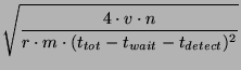
that occurred in the last  seconds are incorrect and
therefore the fraction of failed queries is seconds are incorrect and
therefore the fraction of failed queries is
 . Therefore, to ensure that no more than a fraction . Therefore, to ensure that no more than a fraction  of
queries fail we need: of
queries fail we need:
For a system with  nodes, with a rate of nodes, with a rate of  events events , and , and
 , we get a time interval as large as , we get a time interval as large as  to propagate all
information. Note also that if to propagate all
information. Note also that if  is linearly proportional to is linearly proportional to  ,
then ,
then  is independent of is independent of  . It is only a function of the
desired success rate. . It is only a function of the
desired success rate.
3.2 Slices and Units
Our system performance depends on the number of slices and units:
 is the number of slices the ring is divided into. is the number of slices the ring is divided into.
 is the number of units in a slice. is the number of units in a slice.
Parameters  and and  determine the expected unit size.
This in turn determines determine the expected unit size.
This in turn determines
 , the time it takes for information to propagate
from a unit leader to all members of a unit, given
an assumption about , the time it takes for information to propagate
from a unit leader to all members of a unit, given
an assumption about  , the frequency of keep-alive probes.
From , the frequency of keep-alive probes.
From  we can determine we can determine  from our calculated
value for from our calculated
value for  , given choices of values for , given choices of values for  and and
 .
(Recall that .
(Recall that
 .) .)
To simplify the analysis we will choose values for  , ,
 , and , and
 . As a result our analysis will be concerned with just two
independent variables, . As a result our analysis will be concerned with just two
independent variables,  and and  , given a particular choice of
values for , given a particular choice of
values for  , ,  , and , and  . We will use one second for both . We will use one second for both
 and and  . This is a reasonable decision since the amount of
data being sent in probes and messages to unit leaders is large enough to
make the overhead in these messages small (e.g., information about 20
events will be sent in a system with . This is a reasonable decision since the amount of
data being sent in probes and messages to unit leaders is large enough to
make the overhead in these messages small (e.g., information about 20
events will be sent in a system with  nodes). Note that with
this choice of nodes). Note that with
this choice of  , ,  will be half the unit size. We will use
three seconds for will be half the unit size. We will use
three seconds for
 to account for the delay in detecting
a missed keep-alive message and a few probes to confirm the event. to account for the delay in detecting
a missed keep-alive message and a few probes to confirm the event.
3.3 Cost Analysis
Our goal is to choose values for  and and  in a way that
reduces bandwidth utilization. In particular we are concerned
with minimizing bandwidth use at the slice leaders,
since they have the most work to do in our approach. in a way that
reduces bandwidth utilization. In particular we are concerned
with minimizing bandwidth use at the slice leaders,
since they have the most work to do in our approach.
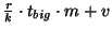
Bandwidth is consumed both to propagate the actual data, and
because of the message overhead.  bytes will be required to
describe an event, and the overhead per message will be bytes will be required to
describe an event, and the overhead per message will be  . .
There are four types of communication in our system.
- Keep-alive messages: Keep-alive
messages form the base level communication between a node and its
predecessor and successor. These messages include information about
recent events. As described in Section 2, our system avoids
sending redundant information in these messages by controlling the
direction of information flow (from unit leader to unit members) and
by not sending information across unit boundaries.
Since keep-alive messages are sent every second, every node that is not on the
edge of a unit will send and acknowledge an aggregate message containing,
on average,  events. The size of this message is therefore events. The size of this message is therefore
 and
the size of the acknowledgement is and
the size of the acknowledgement is  . .
- Event notification to slice leaders:
Whenever a node detects an event, it sends a notification to its slice
leader. The expected number of events per second
in a slice is
 .
The downstream bandwidth utilization on slice
leaders is therefore .
The downstream bandwidth utilization on slice
leaders is therefore
 . Since each message
must be acknowledged, the upstream utilization is . Since each message
must be acknowledged, the upstream utilization is
 . .
- Messages exchanged between slice leaders:
Each message sent from one slice leader to another batches together
events that occurred in the last
 seconds in the slice. The
typical message size is, therefore, seconds in the slice. The
typical message size is, therefore,
 bytes. During any bytes. During any  period, a slice leader sends this
message to all other slice leaders ( period, a slice leader sends this
message to all other slice leaders ( of them), and receives an
acknowledgement from each of them. Since each slice leader receives as
much as it gets on average, the upstream and downstream use of
bandwidth is symmetric. Therefore, the bandwidth utilization (both
upstream and downstream) is of them), and receives an
acknowledgement from each of them. Since each slice leader receives as
much as it gets on average, the upstream and downstream use of
bandwidth is symmetric. Therefore, the bandwidth utilization (both
upstream and downstream) is
- Messages from slice leaders to unit leaders:
Messages received by a slice leader are batched for one second and
then forwarded to unit leaders. In one second,
 events happen and
therefore the aggregate message size is events happen and
therefore the aggregate message size is
 and the
bandwidth utilization is and the
bandwidth utilization is
Table 1 summarizes the net bandwidth use on each
node. To clarify the presentation, we have removed insignificant terms
from the expressions.
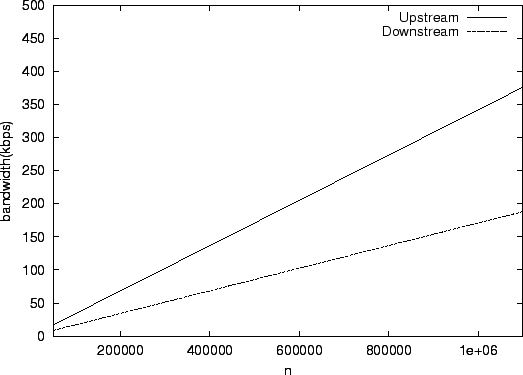
Figure 3:
Bandwidth use on a slice leader with

 |
Using these formulas we can compute the load on non-slice leaders in a
particular configuration. In this computations we use  bytes and bytes and
 40 bytes. In a system with 40 bytes. In a system with  nodes, we see that the load on an
ordinary node is 3.84 kbps and the load on a unit leader is 7.36 kbps
upstream and 3.84 kbps downstream. For a system with nodes, we see that the load on an
ordinary node is 3.84 kbps and the load on a unit leader is 7.36 kbps
upstream and 3.84 kbps downstream. For a system with  nodes, these
numbers become 38.4 kbps, 73.6 kbps, and 38.4 kbps respectively. nodes, these
numbers become 38.4 kbps, 73.6 kbps, and 38.4 kbps respectively.
From the table it is clear that the upstream bandwidth
required for a slice leader is likely to be the dominating and limiting
term. Therefore, we shall choose parameters that minimize this bandwidth.
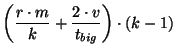
By simplifying the expression and using the interrelationship between
 and and  (explained in Section 3.2) we get a function that depends on
two independent variables (explained in Section 3.2) we get a function that depends on
two independent variables  and and  .
By analyzing the function, we deduce that
the minimum is achieved for
the following values: .
By analyzing the function, we deduce that
the minimum is achieved for
the following values:
Table 1:
Summary of bandwidth use
| |
Upstream |
Downstream |
| Slice Leader |
 |
 |
| Unit Leader |
 |
 |
| Other nodes |
 |
 |
|
These formulas allow us to compute values for  and and  .
For example in a system of .
For example in a system of  nodes we want roughly 500 slices
each containing 5 units. In a system of nodes we want roughly 500 slices
each containing 5 units. In a system of  nodes, we still have
5 units per slice, but now there are 5000 slices. nodes, we still have
5 units per slice, but now there are 5000 slices.
Given values for  and and  we can compute the unit size and
this in turn allows us to compute we can compute the unit size and
this in turn allows us to compute  and and  . We find
that we use least bandwidth when . We find
that we use least bandwidth when
Thus, we choose 23 seconds for  and 23 seconds for and 23 seconds for
 . .
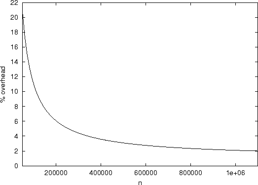
Figure 4:
Aggregate bandwidth overhead of the scheme as a percentage of the theoretical optimum
 |
Given these values and the formulas given in Table 1, we can plot the
bandwidth usage per slice leader in systems of various sizes. The results of this calculation
are shown in
Figure 3. Note that the load increases only
linearly with the size of the system. The load is quite modest in a
system with  nodes (35 kbps upstream bandwidth), and therefore
even nodes behind cable modems can act as slice leaders in such a
system. In a system with nodes (35 kbps upstream bandwidth), and therefore
even nodes behind cable modems can act as slice leaders in such a
system. In a system with  nodes the upstream bandwidth required
at a slice leader is approximately 350 kbps. Here it would be more
appropriate to limit slice leaders to being machines on reasonably
provisioned local area networks.
For larger networks, the bandwidth increases to a point where a slice
leader would need to be a well-provisioned node. nodes the upstream bandwidth required
at a slice leader is approximately 350 kbps. Here it would be more
appropriate to limit slice leaders to being machines on reasonably
provisioned local area networks.
For larger networks, the bandwidth increases to a point where a slice
leader would need to be a well-provisioned node.
Figure 4 shows the percentage overhead of this
scheme in terms of aggregate bandwidth used in the system with respect
to the hypothetical optimum scheme with zero overhead. In such a
scheme scheme, the cost is just the total bandwidth used in sending
 events to every node in the system every second, i.e., events to every node in the system every second, i.e.,
 . Note that the overhead in our system comes from the
per-message protocol overhead. The scheme itself does not propagate
any redundant information. We note that the overhead is approximately
20% for a . Note that the overhead in our system comes from the
per-message protocol overhead. The scheme itself does not propagate
any redundant information. We note that the overhead is approximately
20% for a  sized system and goes down to 2% for sized system and goes down to 2% for  sized
system. This result is reasonable because messages get larger and
the overhead becomes less significant as system size increases. sized
system. This result is reasonable because messages get larger and
the overhead becomes less significant as system size increases.
4 Related Work
Rodrigues et al. [7] proposed a single hop
distributed hash table but they assumed a much smaller peer dynamics,
like that in a corporate environment, and therefore did not have to
deal with the difficulties of rapidly handling a large number of membership
changes with efficient bandwidth usage. Douceur
et al. [2] present a system
that routes in a constant number of hops, but that design assumes
smaller peer dynamics and searches can be lossy.
Kelips [3] uses  sized tables per node and a gossip mechanism to
propagate event notifications to provide constant time lookups.
Their lookups, however, are constant time only when the routing
table entries are reasonably accurate. As seen before, these systems
are highly dynamic and the accuracy of the tables depends on how
long it takes for the system to converge after an event.
The expected convergence time for an event
in Kelips is sized tables per node and a gossip mechanism to
propagate event notifications to provide constant time lookups.
Their lookups, however, are constant time only when the routing
table entries are reasonably accurate. As seen before, these systems
are highly dynamic and the accuracy of the tables depends on how
long it takes for the system to converge after an event.
The expected convergence time for an event
in Kelips is
 . While this will
be tens of seconds for small systems of around a 1000 nodes,
for systems having . While this will
be tens of seconds for small systems of around a 1000 nodes,
for systems having  to to  nodes, it takes
over an hour for an event to be propagated through the system.
At this rate, a large fraction of the routing entries in each table are likely
to be stale, and a correspondingly large fraction of queries would
fail on their first attempt. nodes, it takes
over an hour for an event to be propagated through the system.
At this rate, a large fraction of the routing entries in each table are likely
to be stale, and a correspondingly large fraction of queries would
fail on their first attempt.
Mahajan et al. [5] also derive analytic models for the
cost of maintaining reliability in the Pastry [8]
peer-to-peer routing algorithm in a dynamic setting. This work differs substantially from ours
in that the nature of the routing algorithms is quite
different - Pastry uses only  state but requires state but requires  hops per lookup - and they focus their work on techniques to reduce
their (already low) maintenance cost.
hops per lookup - and they focus their work on techniques to reduce
their (already low) maintenance cost.
Liben-Nowell et al. [4] provide a lower-bound on
the cost of maintaining routing information in peer-to-peer networks that try
to maintain topological structure. We are designing
a system that requires significantly larger bandwidth than in the lower bound
because we aim to achieve a much lower
lookup latency.
5 Conclusion
This paper shows that maintaining only a small amount of routing state at
each node is not necessary in a dynamic peer-to-peer system. We present a design for a system that
maintains complete membership information with reasonable bandwidth requirements.
Currently deployed and proposed systems vary greatly in size and
membership behavior. Corporate and academic
environments have far fewer
configuration events; e.g., half of  machines probed in a
software company are up over 95% of the
time [1]. If we design our system to deal with
these relatively stable environments, we will have much lower bandwidth
requirements. machines probed in a
software company are up over 95% of the
time [1]. If we design our system to deal with
these relatively stable environments, we will have much lower bandwidth
requirements.
For systems of size much greater than a million nodes, routing
tables become large and it may not be desirable to keep them
completely in primary memory.
In such a deployment scenario, we may want to use a two-hop
routing scheme instead: The querying node contacts a node in the slice
containing the target node.
That node then redirects the query to the target node. In such a scheme, the
querying node needs to be aware of only a few nodes of other slices, leading
to smaller routing tables.
It is not
difficult to adapt our approach to such a scheme, with large
savings in bandwidth because very little inter-slice information needs
to be propagated.
Currently peer-to-peer storage systems have high lookup latency and are therefore only
well-suited for applications that do not mind high-latency store and
retrieve operations (e.g., backups) or that store and retrieve massive
amounts of data (e.g., a source tree distribution). Moving to more
efficient routing removes this constraint. This way we can enable a
much larger class of applications for peer-to-peer systems.
Acknowledgements
This research is supported by DARPA under contract F30602-98-1-0237 and
NSF Grant IIS-9802066. R. Rodrigues was supported by a Praxis XXI fellowship.
- 1
-
W. J. Bolosky, J. R. Douceur, D. Ely, and M. Theimer.
Feasibility of a serverless distributed file system deployed on an
existing set of desktop PCs.
In ACM SIGMETRICS, 2000.
- 2
-
J. R. Douceur, A. Adya, W. J. Bolosky, D. Simon, and M. Theimer.
Reclaiming space from duplicate files in a serverless distributed
file system.
In ICDCS, July 2002.
- 3
-
I. Gupta, K. Birman, P. Linga, A. Demers, and R. van Renesse.
Kelips: Building an efficient and stable P2P DHT through increased
memory and background overhead.
In IPTPS, 2003.
- 4
-
D. Liben-Nowell, H. Balakrishnan, and D. Karger.
Analysis of the evolution of peer-to-peer systems.
In PODC, 2002.
- 5
-
R. Mahajan, M. Castro, and A. Rowstron.
Controlling the cost of reliability in peer-to-peer overlays.
In IPTPS, 2003.
- 6
-
S. Ratnasamy, P. Francis, M. Handley, R. Karp, and S. Shenker.
A scalable content-addressable network.
In SIGCOMM, Aug. 2001.
- 7
-
R. Rodrigues, B. Liskov, and L. Shrira.
The design of a robust peer-to-peer system.
In SIGOPS European Workshop, 2002.
- 8
-
A. Rowstron and P. Druschel.
Pastry: Scalable, decentralized object location, and routing for
large-scale peer-to-peer systems.
In IFIP/ACM Middleware, Nov. 2001.
- 9
-
S. Saroiu, P. K. Gummadi, and S. D. Gribble.
A measurement study of peer-to-peer file sharing systems.
In MMCN, Jan. 2002.
- 10
-
I. Stoica, R. Morris, D. Karger, F. Kaashoek, and H. Balakrishnan.
Chord: A scalable Peer-To-Peer lookup service for internet
applications.
In ACM SIGCOMM, Aug. 2001.
- 11
-
B. Y. Zhao, J. D. Kubiatowicz, and A. D. Joseph.
Tapestry: An infrastructure for fault-tolerant wide-area location and
routing.
Technical Report UCB/CSD-01-1141, UC Berkeley, Apr. 2001.
One Hop Lookups for Peer-to-Peer Overlays
This document was generated using the
LaTeX2HTML translator Version 2K.1beta (1.47)
Copyright © 1993, 1994, 1995, 1996,
Nikos Drakos,
Computer Based Learning Unit, University of Leeds.
Copyright © 1997, 1998, 1999,
Ross Moore,
Mathematics Department, Macquarie University, Sydney.
The command line arguments were:
latex2html -split 0 -no_navigation -white -t 'One Hop Lookups for Peer-to-Peer Overlays' -no_reuse -show_section_numbers onehop.tex
The translation was initiated by Anjali Gupta on 2003-06-18
Anjali Gupta
2003-06-18
|