A Spin-Up Saved is Energy Earned: |
Abstract: Storage accounts for a significant amount of a data center’s ever increasing power budget. As a consequence, energy consumption has joined performance and reliability as a dominant metric in storage system design. In this paper, we show that the structure of an erasure code— which is generally used to provide data reliability—can be exploited to save power in a storage system. We define a novel technique in power-aware systems called power-aware coding and present generic techniques for reading, writing and activating devices in a power-aware, erasure-coded storage system. While our techniques have an effect on energy consumption, fault tolerance and performance, we focus on a few examples that illustrate the tradeoff between power efficiency and fault tolerance. Finally, we discuss open problems in the space of power-aware coding.
Traditionally, storage systems are measured in terms of performance and reliability. Due to the increasing amount of data stored in recent years and the significant amount of power required to store such data, a great deal of work has gone into measuring and minimizing the power consumption of storage systems [2, 12, 15, 6, 14, 11]. Storage accounts for roughly 27% of a data center’s power budget [1]; thus, proactively activating and deactivating disks can effectively lower the energy footprint of a data center.
Almost every storage system generates redundancy to provide data reliability in the face of failures. In most cases, an erasure code is defined across a group of disks to provide reliability. When a disk fails within a group, other disks in the group are used to recompute the contents of the failed disk.
In addition to providing fault tolerance, erasure codes may also be used to prevent disk activation. We call this technique power-aware coding. Consider the case where all disks are working correctly (no failures). If the system can tolerate the failure of any single disk in the group, then one disk can remain inactive for an extended period of time and need not be activated if a read request is directed to the inactive disk. Instead of activating the disk, its contents can be reconstructed from the active disks.
The number of active disks required to reconstruct the contents of one or more inactive disks is determined by the erasure code. Given k data disks, the class of codes, called maximum distance separable (abbreviated MDS and explained in Section 2), require at least k active devices to reconstruct the contents of an inactive device. While any erasure code may be used to save power, we believe that another class of codes, called non-MDS, are best suited for power-aware coding because less than k active devices are generally required to rebuild the contents of an inactive device.
To date, a handful of power-aware redundancy techniques have been proposed. Pinheiro et al. place data and parity on different disks; deactivating parity disks during light loads and staging parity updates in non-volatile RAM [6]. PARAID is a power-aware disk array architecture that trades logical capacity for power efficiency by replicating blocks from inactive disks onto spare regions of active disks [12]. e-RAID introduced the idea of transformed reads for RAID-1 and RAID-5, which allows the system to rebuild the contents of an inactive disk from cache, other active disks, or both [11].
Our work is similar to e-RAID, which prevents activation under RAID-1 and RAID-5. Both RAID-1 and RAID-5 have trivial solutions with respect to servicing read requests from inactive devices: redirect the request to an active mirror or recompute from the active devices, respectively. The RAID-1 technique trades a great deal of space for power efficiency; the RAID-5 technique is limited in utility, since all but one disk must be active to service any read. Recent analysis suggests that storage systems should have the ability to tolerate more than one failure [3], indicating the need for codes that provide more fault tolerance than RAID-5. The power-aware coding techniques we propose and the associated problems we identify apply to any erasure code.
The contributions of this work are fourfold. First, we present power-aware coding, which provides a way to evaluate the tradeoff between fault tolerance and power efficiency in storage systems. Second, we discuss challenges and initial work within the scope of power-aware coding including writing, reading and activating disks in an erasure-coded, power-aware storage system. Third, we present an example to illustrate tradeoffs in power-aware, erasure-coded storage systems. Finally, we discuss open problems in the space of power-aware coding.
An erasure code is made up of codewords that have n symbols. Storage systems typically use systematic erasure codes, where each codeword contains k data symbols and m=n−k parity (redundant) symbols. A code symbol generally refers to a sector or set of sectors on a single storage device. The Hamming distance of a code provides a compact representation of fault tolerance. Any set of failures strictly less than the Hamming distance may be tolerated. Traditionally, storage systems use maximum distance separable (MDS) codes, which provide optimal fault tolerance by having a Hamming distance of m+1 (they can tolerate up to m failures out of n symbols). In this work we focus on so-called flat-codes: codes that map exactly one symbol per codeword to a device.
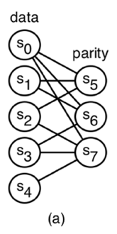
Figure 1: A flat XOR-based code with 5 data symbols and 3 parity symbols. Each symbol is mapped to a unique disk.
Any code that is not MDS is called non-MDS. While MDS codes can tolerate up to any m failures, the Hamming distance of a non-MDS code is strictly less than m, but may tolerate some failures at or beyond the Hamming distance. In this paper, we focus on a class of non-MDS codes called flat XOR-based codes [13]. An example of a flat XOR-based code is shown in Figure 1-a. This code is described by a bipartite graph, called a Tanner graph [10]. The data symbols form the left nodes in the graph, while the parity symbols are the right nodes. A data symbol contributes to a parity symbol if an edge connects the corresponding nodes in the graph. The parity equations are derived by following the edges connected to each parity node in the graph. For instance, the parity node for symbol s5 is adjacent to s0, s1 and s2, therefore, we compute s5 as s0⊕ s1 ⊕ s2. From the graph, we see that s6 is computed as s0⊕ s1 ⊕ s3 and s7 is computed as s0⊕ s2 ⊕ s3 ⊕ s4.
Since we consider only systematic codes, a k × n generator matrix, G, is used to compute the m=n−k parity symbols from k data symbols. The first k columns of the matrix form a k × k identity matrix. The last m columns are used to compute each of the m parity symbols from the data symbols. Thus, every systematic generator matrix will have the form G=(Ik | P), where the elements of the matrix are taken from a finite field. A codeword is computed as d · G=c, where d is a 1 × k vector containing the k data symbols.
The Tanner graph of the flat XOR-based code shown in Figure 1-a is transformed into a generator matrix by creating a column for each node in the graph . The nodes s0, s1, s2, s3 and s4 form the first five columns, where the column for symbol si is the unit vector with a 1 in the i-th element. A parity column (s5, s6 and s7) is a linear combination of the columns that correspond to the data symbols involved in the parity equation. For example, the column corresponding to symbol s5 is the sum of the 0th, 1st and 2nd columns of the matrix.
The generator matrix for an MDS code is typically created by starting with a specific type of matrix (i.e. Vandermonde) and performing elementary matrix operations to transform the matrix into one of the form (Ik |P), where the entries of the matrix are in the finite field of 28, 216 or 232 elements.
While non-MDS codes are not as fault-tolerant as MDS codes with the same number of data and parity symbols, rebuild of a single symbol typically involves less than k symbols. This is not the case for MDS codes, where k available symbols are required to reconstruct the contents of 1 to m symbols. The suitability of non-MDS codes to power-aware storage follows from this observation—data symbols on inactive devices may be reconstructed from fewer active devices compared to MDS codes.
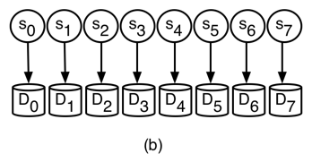
We define power-aware coding in terms of a set of disks and an erasure code instance across the disks. An erasure code instance is a mapping of erasure-coded symbols—data or parity—to disks. An example code instance is shown in Figure 1-b. As shown, we assume that the number of symbols in a codeword is equal to the number of disks and each symbol is mapped to a unique disk. In this case, each code symbol, si, is mapped to disk Di. For brevity, we assume that all disks have the same capacity and characteristics; however, our techniques have the ability to support disks with different characteristics.
The crux of power-aware coding is to prevent spinning up inactive disks when servicing read requests by treating each inactive disk as an erasure. As an example, consider the setup shown in Figure 1. Suppose disks D0, D5, D6 and D7 are currently active; all others are inactive. If the system receives a read request for disk D4 we can service the request as D0 ⊕ D5 ⊕ D6 ⊕ D7 instead of activating disk D4, since s4=s0 ⊕ s5⊕ s6 ⊕ s7. The comparable MDS code with 5 data disks and 3 parity disks would require a disk activation, since 4 active devices are not sufficient to recover the contents of an inactive device.
Three conditions are necessary for an erasure-coded system to be power-aware. First, the system must have policies that service writes in a way that minimizes operational power consumption, while maintaining a sufficient level of reliability. Second, a read policy will dictate if data is accessed directly off a disk or reconstructed using redundant information. Finally, when disk activation is necessary to service a read request, a policy is needed to determine how to schedule disk activations in a power-efficient manner.
We assume the system has a total of N disks; thus, there are a total of N/n code instances. Writes into the system are serviced by deterministic disk activations. A write group is a list of disks that will be active within a single code instance at the same time to perform this function. Every disk in the system must be a member of at least one write group and will most likely belong to several write groups. When a write group is active, its disks are also active. Exactly one write group per code instance will be active at a time. Each write group is identified by a tuple containing a unique id, a begin time and an end time. A power schedule is a list of these tuples; thus, it temporally specifies how disks are deterministically activated and deactivated within a code instance.
Servicing writes via write groups assumes that the storage system is write-anywhere or defers writes, since writes are only handled by disks in the current write group. Approaches such as Pergamum [9] and write off-loading [5] also use these techniques to save power.
The total power consumed by the storage system is heavily dependent on the power schedule. A write group will likely be active for a number of hours and keep the number of active disks to a minimum. In addition, the number of active disks determine which data can be reconstructed; thus, a proper balance is required to service both writes and reads into the system.
Read requests are satisfied by either accessing an active disk or reconstructing the appropriate content using the active disks (via the erasure code). In some cases, the information provided on the active disks will be insufficient for serving the request. A transient disk activation occurs when a disk must be activated to service a read request. A transient activation may be used to directly service the request or as part of data reconstruction if the request involves multiple disks. Since a transient activation involves a disk that is not a member of the current write group, it will be deactivated after some fixed period and will not service writes. In addition to reads, transient activations may also be used to perform background operations such as disk scrubbing [8].
Choosing to perform reconstruction, transient activation or a combination of the two depends on the environment and workload. There may be cases where a transient activation may be more power efficient than reconstructing the data from active disks. The system should optimize for each read request based on the state of the system and number of disks involved.
Most systems handle read requests to inactive disks using the naive strategy, which simply activates the disks involved in the request. A great deal of transient activations can have a dramatic effect on system power consumption and reliability. In addition, recent analysis shows that the system reliability will decrease if disks are power cycled too often [8]. In order to minimize power consumption and maintain a reasonable level of reliability, the system should minimize the number of transient disk activations.
In this section we cover initial policies for servicing writes, servicing reads and handling transient disk activations. These policies serve as a starting point for constructing erasure-coded, power-aware systems.
Each of the N/n code instances in the system must have a policy for generating its own write groups. Consider a simple policy, called single-data connected-parity, for constructing write groups. Under this policy, write groups are generated based on the parity equations for the code instance. A write group is generated for each data disk. We assign each data disk, Di, to a unique write group, Wi. A parity disk Dj is added to write group Wi if Di contributes to the parity equation for Dj. This policy is biased towards writes because it allows all parity updates to immediately complete, since a data disk and its associated parity disks will be active at the same time. Under this policy, the write groups for the code instance in Figure 1 would be {D0,D5,D6,D7}, {D1,D5,D6}, {D2,D5,D7}, {D3,D6,D7} and {D4,D7}. If every code instance implements this policy, then data may be written in parallel across N/n disks. Write groups may be defined by more than one data disk in environments that must sustain heavy write workloads.
The duration of a write group—calculated by subtracting the end time entry from the begin time entry in the write group’s corresponding tuple—is a tunable parameter based on utilization, workload and frequency of integrity checks. For this reason, analyzing the appropriate duration of a write group is left to future work.
At a high level, the power-aware read algorithm treats inactive devices as erased and relies on matrix methods to determine if partial or whole-stripe reconstruction is possible using disks that are already active [4]. If reconstruction of any erased data is possible, the matrix transformations result in appropriate recovery equations. Instead of marking a disk as failed (or erased), we mark all inactive devices tentatively lost. A tentatively lost device is made available through activation. When a read request involves data that is tentatively lost, we try to reconstruct the elements in a way that minimizes the number of disk activations.
Our read algorithm relies on a function that determines if lost data is recoverable, and if so, the equations needed to reconstruct. The recovery equations for tentatively lost data are computed using the underlying generator matrix, G. A matrix, G′, is constructed by zeroing out the columns in G that correspond to the tentatively lost elements. In order to determine the recovery equations we must find a pseudo-inverse, R (as defined by Hafner et al. [4]), of G′. Suppose the vector c′ is the vector c=d · G with zeroes in the positions corresponding to tentatively lost elements. Then c′ · R=d′, where the non-zero elements of d′ are the corresponding recoverable elements of d and the zero elements are unrecoverable. In this case, R contains the recovery equations and c′ contains the available data and parity symbols.
The power-aware read algorithm is shown in Algorithm 1. The algorithm takes the inactive disks involved in the read request (I), the generator matrix for the underlying code (G) and the set of currently inactive devices (L) as input. The function recoverable uses the aforementioned matrix methods to determine the disks that are recoverable based on the underlying code and the set of currently available (or recoverable) disks. The recoverable function returns a list of recoverable disks, L′, and the corresponding recovery equations. The activate_disk function, which is explained in Section 4.3, determines the disk (or disks) to activate given the read request and state of the system.
As an example, suppose I={D2,D4} and L={D1,D2, D3,D4} in the code instance shown in Figure 1. In the first iteration, recoverable returns ({D4=D0⊕ D5 ⊕ D6 ⊕ D7}, {D4}). The second iteration begins with I={D2} and L={D1,D2, D3} and recoverable returns (∅,∅), therefore, a disk must be activated. Since D2 is the only disk left in I, activate_disk returns ({D2=D2}, {D2}). The loop invariant evaluates to false at the beginning of the third iteration and the algorithm returns the corresponding recovery equations.
Algorithm 1: Recover I using G and L
Since our approach takes advantage of the underlying erasure code, there exist many cases where the naive activations can be avoided. If the read request contains a single inactive disk that cannot be reconstructed, then we simply activate that disk. If more than one inactive disk is in a read request, we must determine the minimum number of activations required to service the request.
Algorithm 2 performs a brute force search of potential disks to activate by generating all possible combinations of disk activations (i.e. powerset of inactive disks). The powerset function, P, orders the combinations in ascending order by size. For each combination, s, the algorithm determines if the request can be satisfied when the disks listed in s are activated (via is_fully_recoverable). Once a satisfactory combination is chosen, the algorithm returns the disks to activate and an updated list of inactive devices. Since the combinations are ordered, this algorithm will return the minimum number of activations needed to service the request.
Algorithm 2: Determine the minimum number of disk activations required to service request I when disks in L are inactive.
In this section, we clarify a few of the tradeoffs and illustrate the utility of non-MDS codes for power-efficiency in a small system containing 8 disks. We have chosen three erasure codes to illustrate the various tradeoffs in terms of power consumption and fault tolerance: (5,3)-flat, (4,4,2)-flat and (6,2)-mds. The (5,3)-flat code is the code shown in figure 1. The (6,2)-mds is an MDS code with 6 data symbols and 2 parity symbols. The (4,4,2)-flat is a flat XOR-based code with data symbols s0, s1, s2 and s3, where each data symbol is connected to exactly 2 parity symbols. The parity equations of (4,4,2)-flat are: s4 = s2 ⊕ s3, s5 = s0 ⊕ s3, s6 = s0 ⊕ s1 and s7 = s1 ⊕ s2. As we will see later in this section, these codes were chosen due to similar, but not identical, fault tolerance properties.
We assume all disks are identical and Pr, Pa and Pi is the power (in watts) consumed by each disk when reading, active but not reading and inactive, respectively. Furthermore Na and Ni represent the number of active and inactive disks in the system. A read request of size R (MB) takes a disk with transfer rate DR (MB/s) and average rotational latency DL (s) approximately TTS=DL+R/DR seconds to service. Finally, each disk consumes Psp watts during a transition from inactive mode to active mode, which takes Tsp seconds. We leave the energy calculation for CPU, network, and so on to future work.
Our analysis utilizes the energy consumption values of an IBM Ultrastar 36Z15. The values are: Pr=13.5 W, Pa=10.2 W, Pi=2.5 W, DR=55 MB/s, Psp=13.5 W, Tsp=10.9 s and DL=2 ms.
We consider four possible system configurations. System A uses the (5,3)-flat code and the single-data connected-parity write group policy. System B uses the (6,2)-mds code and the single-data connected-parity write group policy. System C uses the (6,2)-mds code and a write group policy similar to e-RAID, where all but two disks are active. Finally, system D uses the (4,4,2)-flat and the single-data connected-parity write group policy.
We estimate the power consumption of each system configuration due to a given write group policy and erasure code. To simplify the analysis, we approximate the energy consumption without considering the workload. We believe that our calculation, while inaccurate in an absolute sense, is sufficient for comparison. We understand that detailed simulation is required to obtain accurate energy consumption numbers.
Each system will have Na active devices and Ni inactive devices. On average, each system will consume approximately (Na· Pa)+(Ni· Pi) watts. System A and D have, on average, 3 devices active and each consume approximately 43.1 W. Systems B and C will have 3 and 6 devices active at all times and consume 43.1 W and 66.2 W, respectively. The logical (usable) capacity of each system can be used to normalize to watts-per-data-disk. The normalized energy consumption of each system is: system A is 8.62 W, system B is 7.18 W, system C is 11.03 W and system D is 10.78 W.
Each of the three systems have different capabilities in terms of reconstructing data present on inactive devices. System C has the ability to service any read request without activating any disks, since 6 active disks is sufficient to reconstruct the contents of any two inactive disks. Similarly, system B needs at least 6 active devices to reconstruct the contents of an inactive disk. Every write group in system B contains 3 disks; thus, system B will most likely not have the ability to service reads via reconstruction.
The reconstruction capability of system A sits somewhere between that of system B and C. For instance, while the write group containing D0, D5, D6 and D7 is active, any request to D4 can be serviced without activating any disks, because D4=D0 ⊕ D5 ⊕ D6 ⊕ D7. As another example, suppose a read request is directed at D2 and D3 under the same write group. While a similar request in system B would require activating both disks, only a single disk activation (D2) is required to service the request in system A, since D3=D2⊕ D5 ⊕ D6.
The reconstruction capability of system D highlights the tradeoff between storage efficiency and prospective power savings. For example, if the write group containing D0, D5 and D6 is active, all but one data symbol can be reconstructed: D1=D6 ⊕ D0 and D3=D0 ⊕ D5. The symmetric structure of this code makes this true for all write groups. One could argue that the same reconstruction ability is possible by simply activating three data disks, but there would be no parity disks active to service writes into the system. This code illustrates a nice balance when optimizing power efficiency for both reads and writes.
In order to evaluate the efficacy of our read policies, we calculate the approximate power consumption when a 50 MB read request is targeted at a single inactive disk. We save more complicated cases, such as combining activation and reconstruction, for future work. System A, C and D will service the read request by either activating the disk or performing partial reconstruction. System B must activate the disk to service the request. The approximate power (in Joules) required when activating a disk to service the request is
| (Psp · Tsp | ) | + | (TTS · | (Na· Pa+Ni· Pi+ Pr)) | , |
where the first term in the summation represents the power consumed to activate the disk and the second term is the power consumed when servicing the request. The disk activation power consumption of systems A, B and D is 198.71 J, since all systems have, on average, 3 disks activated at any given time. The power consumption of system C is approximately 219.76 J. Note that these power consumption numbers are highly dominated by the power required to spin-up an inactive disk, thus avoiding such activations is crucial.
If the contents of the inactive disk can be reconstructed from the active disks, we can approximate the power consumed as (TTS · (Na· Pr+Ni· Pi)). In this case, we assume that all active disks participate in the rebuild operation. To be fair, we assume Na=4 for system A, since 4 disks must be active to perform reconstruction under the single-data connected-parity policy. The reconstruction power consumption of systems A, C and D are 58.30 J, 78.35 J and 48.28 J, respectively. Since system B cannot reconstruct the contents of any inactive disks, it must consume 198.71 J.
We chose the three codes in this example due to similar fault tolerance properties. The (6,2)-mds is space-optimal and has the ability to tolerate any 2 disk failures. The (5,3)-flat code can tolerate all but one 2 disk failure (the failure of D4 and D7), thus it is not quite as fault tolerant as the (6,2)-mds code. Finally, the (4,4,2)-flat can tolerate any 2 disk failures, all but four 3 disk failures and all but five 4 disk failures. In this case we see that a system designer must trade both fault tolerance and space for power efficiency.
It is important to point out the tradeoff between power efficiency, fault tolerance and space efficiency. The (6,2)-mds code provides optimal fault tolerance for 6 data and 2 parity elements, but lacks flexibility in terms of potential power savings; at least 6 devices must be active in order to reconstruct the contents of any inactive device. The (5,3)-flat code is not as space efficient or fault tolerant as (6,2)-mds, but provides more opportunities to recover data off inactive devices. By trading even more space, the (4,4,2)-flat code is more fault tolerant than the other codes analyzed and provides many opportunities to exploit redundancy for power savings. While we cannot make any sweeping generalizations, we believe this example motivates further analysis when trading power consumption, fault tolerance and space efficiency.
Introducing the power-aware coding technique, its terminology and a few motivating examples is only a first step. There are three forms of open problems in this area: determining which environments will benefit from power-aware coding, finding optimal policies and erasure codes for a given environment and developing robust metrics for evaluating the power-reliability-performance tradeoff.
The problem of finding optimal policies and erasure codes is heavily dependent on workload and is very difficult to solve analytically; the optimization must trade power consumption, reliability and performance. In addition, considering reconstruction in terms of both actual failures and a read policy remains an open problem. To gain insight in these areas, we hope to experiment with standard algorithms in the area of constraint satisfaction problems [7] and are currently building a simulation environment to determine the utility of power-aware coding in a variety of settings. Initial results show that power-aware coding may be well suited for the write-once, read-maybe workload of long-term archival storage systems.
The metrics used in this paper estimate power consumption and only account for the power consumed by disks. In addition to accounting for other energy consumers, such as CPUs, finding accurate metrics for evaluating the power-reliability-performance tradeoff remains an open problem.
[*] Supported in part by the Petascale Data Storage Institute under Dept. of Energy award FC02-06ER25768 and by the industrial sponsors of the Storage Systems Research Center.