 |

 |
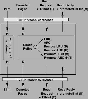
We implemented CacheSim (Figure 7), a framework
which allows us to benchmark various algorithms
for a wide range of cache sizes, real-life traces, and any single and multi-path
hierarchy. CacheSim is instantiated with a given cache size and
one of the following policies: LRU, ARC, DEMOTE-LRU, DEMOTE-ARC,
PROMOTE-LRU, and PROMOTE-ARC. One instance of CacheSim simulates one level of
cache in a multi-level cache hierarchy, while communicating to the higher and lower
caches over a TCP/IP network.
The highest level reads requests from a trace file one I/O (size ![]() bytes) at a time, with no thinktime, while the lowest level simulates disk responses with a fixed response time.
bytes) at a time, with no thinktime, while the lowest level simulates disk responses with a fixed response time.
Apart from the traditional read interfaces, CacheSim also implements two special interfaces:
CacheSim simulates the following realistic
roundtrip response times for storage system hierarchies (based on our knowledge):
For two-level scenarios: ![]() =
= ![]() ms,
ms, ![]() =
= ![]() ms,
ms, ![]() =
= ![]() .
For three-level scenarios:
.
For three-level scenarios: ![]() =
= ![]() ms,
ms, ![]() =
= ![]() ms,
ms, ![]() =
= ![]() ms,
ms, ![]() =
= ![]() ms. The results in this paper are applicable for any set of values where
ms. The results in this paper are applicable for any set of values where
![]() .
.