
| Pp. 91–100 of the Proceedings |  |
KLAT2's Flat Neighborhood Network
H. G. Dietz and T. I. Mattox
Electrical Engineering Department, University of Kentucky, Lexington, KY 40506-0046
KLAT2, Kentucky Linux Athlon Testbed 2, is a cluster of 64 (plus two ``hot spare'') 700MHz AMD Athlon PCs. The raw compute speed of the processors justifies calling the system a supercomputer, but these fast nodes must be mated with a high-performance network in order to achieve the balance needed to obtain speed-up on real applications. Usually, cluster networks are built by combining the fastest available NICs and switching fabric, making the network expensive. Instead, KLAT2 uses a novel ``Flat Neighborhood'' network topology that was designed by a genetic algorithm (GA). A total of about $8,100 worth of 100Mb/s Fast Ethernet NICs, switches, and Cat5 cable, allows KLAT2's network to deliver both single-switch latency for any point-to-point communication and up to 25.6Gb/s bisection bandwidth. This paper describes how this new network architecture was derived, how it is used, and how it performs.
Since February 1994, when we built the first parallel-processing Linux PC cluster, we have been very aggressively pursuing any hardware and software system technologies that can improve the performance or give new capabilities to cluster supercomputers. Thus, when AMD released the first PC processors with vector floating point support (the K6-2's single-precision 3DNow! instruction set), we quickly developed compiler technology to support the use of these multimedia-oriented instructions for general vector/SIMD parallel computing. The result has been a strong relationship with AMD in which they have supported our research work in a variety of ways. Most recently, AMD donated sixty-six 700MHz Athlon processors to our work.
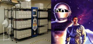
We have used these processors to build KLAT2 (Kentucky Linux Athlon Testbed 2). The name is a reference to the advanced alien who came to the earth in The Day The Earth Stood Still to warn the people of the earth that if they did not immediately stop fighting among themselves, the planet would be destroyed; the earth's destruction is narrowly averted with the famous command to Klaatu's robot: ``Gort, Klaatu Barada Nikto!'' KLAT2, Gort, and Klaatu are shown in the photo.
Our goal for KLAT2 was to build a system that can coordinate the Athlons well enough to reach the performance range seen in the list of the ``Top 500'' supercomputers (https://www.top500.org/). In fact, KLAT2's single-precision LINPACK benchmark performance would rank it 197th in the June 7, 2000 list.
There never was any doubt that Athlon PCs would be very capable supercomputer nodes. However, it was not clear how we could create a cluster network that would balance that performance; AMD only donated Athlon modules -- our meager budget would have to cover the cost of turning the processors into complete systems and networking them together. The cost of the motherboards, memory, and cases were all reasonable, but what about the network?
PAPERS (https://aggregate.org/) is a low-latency network that we have developed through 18 generations of custom hardware since 1994. It is cheap enough for use in KLAT2. However, PAPERS only solves part of the network problem. Although the 3us latency PAPERS achieves is impressive, the aggregate function communication that PAPERS provides is not designed to send blocks of data from one PC to another; a different network is needed for high-bandwidth messaging.
We tried approaching several makers of Gb/s network technologies for donations and/or discounts. However, both the donations and discounts that we were offered were insufficient to satisfy our requirements. The cheapest of the Gb/s NICs that we found were PCI Ethernet cards priced under $300 each, but even that cost would have stretched our budget. Adding to that the cost of a hierarchy of Gb/s switches brings any solution based on Gb/s NICs over $2,000 per PC connected. Further, the switch hierarchy multiplies latency and a tree topology dramatically limits bisection bandwidth. We needed a new solution.
When no solution seems to work, it is time to rephrase the problem. We wanted to have the minimum possible latency between any pair of PCs. Clearly, you couldn't put 65 NICs in each machine to implement a direct connection... the next best thing would be to have just one switch delay between any two PCs. The problem then becomes that a 66-way switch that can handle communication at full wire-speed is not cheap.
You can buy a wire-speed 32-way 100Mb/s switch for about $525. Thus, we could use 32 dual-processor PCs and channel bonding of multiple NICs (https://www.beowulf.org/). Although dual-processor PCs using Intel processors are competitively priced, they divide the node memory bandwidth between the two processors, delivering significantly lower performance than two uniprocessor PCs would for many codes. Even if we wanted to adopt that solution, dual-Athlon PCs are not yet widely available.
The ``Flat Neighborhood'' network topology came from the realization that it was sufficient to share at least one switch with each PC -- all PCs do not have to share the same switch. A switch defines a local network neighborhood, or subnet. If a PC has several NICs, it can belong to several neighborhoods. For two PCs to communicate directly, they simply use NICs that are in a neighborhood that the two PCs have in common. Coincidentally, this flat, interleaved, arrangement of the switches results in unusually high bisection bandwidth -- approaching the same bisection bandwidth that we would have gotten if we had wire-speed switches that were wide enough to span the entire cluster! We even get the benefit that, because four NICs are available for simultaneous use in each PC, we bypass some of the I/O serialization that using IP would imply with a single Gb/s NIC (or channel-bonded set of NICs) under Linux.
Unfortunately, flat neighborhood networks introduce several interesting new problems. Using KLAT2's network as the primary example, the remainder of this paper discusses:
Conceptually, it is very simple to design a flat neighborhood network wiring pattern. For example, for 6 PCs, each with 2 NICs, using 4-way switches:
Thus, A and B are both connected to switches 0 and 1, C and D to switches 0 and 2, and E and F to switches 1 and 2. For A to send to C, it uses switch 0. For A to send to B, it can use either switch 0, switch 1, or both.
In practice, it is useful to reserve one port on each switch for connection to an ``uplink switch.'' This switch is not used in normal operation of the cluster, but provides a very efficient means for communication between the cluster and other systems as well good support for broadcast/multicast. Thus, the above FNN would really be built using 5-way switches and wired as:

Although the use of an uplink switch does not complicate the design problem, the complexity of the design problem does explode when a larger system is being designed with additional, secondary, optimization criteria (such as maximizing the number of switches shared by PCs that communicate in various patterns). Because this search space is very large and the optimization criteria are very general (often requiring simulation of each potential network design), use of a genetic search algorithm is much more effective than other means. The complete GA network design process is described in [1]. Basically, the current version of our GA search uses:
The GA program, written in C, uses SIMD-within-a-register parallelism when executed on a single processor system, but also can be executed in parallel using a cluster. KLAT2's current network design was actually created using our first Athlon cluster, Odie -- four 600MHz PCs.
One of the worst features of flat neighborhood networks is that they are physically difficult to wire. This is because, by design, they are irregular and have very poor physical locality between switches and NICs. The GA design process could be made to include a model of physical wiring locality/complexity in its search, but the resulting designs would probably sacrifice some performance in return for the reduction in wiring difficulty.
KLAT2's PCs are housed in four standard 48"x18"x72" shelving units. The network for KLAT2 consists of ten rack-mounted 32-way (really 31-way plus one uplink port) wire-speed 100Mb/s Fast Ethernet switches. Nine of these switches form the flat neighborhood network's switching fabric; the tenth is used exclusively for (1) I/O to other clusters, (2) multicast, and (3) connection of the two ``hot spare'' Athlon PCs. Thus, KLAT2's network connects 264 NICs and ten switches in a seemingly random pattern spanning five physical racks. Worse still, because we were initially missing some network hardware, we actually implemented one wiring pattern and then rewired the system when the rest of the network hardware arrived.
So, how did we physically wire KLAT2? The basic trick involves recognition of the fact that it doesn't mater which switch port each NIC is connected to. Each of the ten switches was assigned a color that was used for all the cables connected to that switch. For each of the PCs, we simply had our GA print out the network design in the form of a label for each PC showing the cable colors that should be plugged into that PC's NICs:
Wiring the cluster with the GA design took no more than a few minutes per PC, including the time to neatly route the wires between the PC and the switches. In fact, we re-ran the GA to optimize for the communication patterns of the DNSTool CFD (Computational Fluid Dynamics) code [4] and physically re-wired the entire system in less than a few hours. The new design is:
The original physical wiring pattern looks like:
The fundamental problems in flat neighborhood network routing are conceptually simple, but break many assumptions made by network software -- especially IP-based software. In terms of KLAT2's network in particular:
Our basic routing solution is fairly straightforward. Briefly, we have:
A brief summary of the GA-generated basic routing tables follows. Each row corresponds to a particular PC's routing table; each entry specifies which of the nine neighborhood subnets would be used to communicate with the corresponding other PC.

The basic routing concern is to ensure that communications between a pair of machines go through a single switch; however, many pairs of machines have multiple choices for single-switch connections. For example, KLAT2's nodes k00 and k01 actually have three switches in common, not just one. Thus, a technique resembling channel bonding, but much more complex, can be used to provide up to three times the single-link bandwidth between k00 and k01. In fact, using either PCs or the tenth switch, we can get four times the single-link bandwidth between k00 and k01, although latency on one of the paths will be significantly higher than on the other three.
At this writing, we have determined a reasonable implementation technique for advanced routing (see [1]), but have not yet experimented with it. The technique involves encoding all the viable paths and using a modified lookup procedure to determine the set of paths to use; it ignores any paths that would pass through PCs (i.e., does not use PCs as routers). We intend to add this new lookup procedure to an active message library that we will be building for KLAT2's RealTek-based Fast Ethernet NICs.
To better understand the differences between FNNs and other network architectures, it is useful to perform side-by-side comparisons. The first comparison is based purely on the performance predicted using a relatively simple model. The second comparison uses a variety of standard benchmarks that were executed using KLAT2 with two different routing rules: one using the basic FNN routing, the other treating the FNN with its uplink switch as a tree.
Since large FNNs in general, and the one used in KLAT2 in particular, lack symmetry that would facilitate closed-form analysis, it is most effective to begin with analysis of a symmetric network for a smaller system. Thus, let us first consider interconnection network designs that can be built using four-way switches for an eight-PC cluster.
Among the many different topologies proposed for interconnection networks, fat trees have become very popular because they easily provide the full bisection bandwidth. Assuming that appropriate switches are available, the eight-PC network would like like:
For this fat tree, the bandwidth available between any pair of PCs is precisely that of one link; thus, we say that the pairwise bandwidth is 1.0 link bandwidth units. The bisection bandwidth of a network is determined by dividing the machine in half in the worst way possible and measuring the maximum bandwidth between the halves. Because the network is symmetric, it can be cut arbitrarily in half; the bisection bandwidth is maximal when all the processors in each half are sending in a permutation pattern to the processors in the other half. Thus, assuming that all links are bidirectional, the bisection bandwidth is 8*1.0 or 8.0.
Pairwise latency also is an important figure of merit. Latency introduced by the software interface and NIC is essentially independent of interconnection topology, thus we can ignore this factor when comparing alternatives. In addition, if the cluster nodes are physically near each other, we can ignore the wire latency and simply count the average number of switches a message must pass through. Although some paths have only a single switch latency, e.g. between A and B, most paths pass through three switches. More precisely, from a given node, only 1 of each of the 7 other nodes can be reached with a single-switch latency. Thus, 1/7 of all pairs will have 1.0 switch latency and 6/7 will have 3.0 switch latency; the resulting average is (1.0 + 3.0*6)/7, or 2.7 switch latency units.
Unfortunately, most inexpensive switches cannot handle routing for a fat tree topology. The problem lies in the fact that the switches within the fat tree must be able to balance load using multiple paths between the same two network addresses or subnets. Thus, if switch cost is to be kept competitive, the fat tree arrangement generally is not viable for technologies like Fast Ethernet. In fact, the best conventional topology that most commodity switches were designed to support is a simple tree, such as:
It is not difficult to see that latency of the tree is very similar to that of the fat tree. For some communication patterns, including all those in which only a single PC pair are communicating, the tree does yield 1.0 link bandwidth units for communication between a PC pair. More often in parallel programs, only a fraction of link bandwidth is available because multiple pairwise communications are sharing the bandwidth of the 4 links to the top-level switch. The bisection bandwidth is thus approximately half that of the fat tree. The primary advantage is simply the ability to use dumber, cheaper, switches; the primary disadvantage is poorer performance.
Now consider using a FNN to connect these same eight PCs with four-way switches. Like the tree configuration, the FNN easily can use cheap, dumb, switches that could not implement fat tree routing; in fact, the FNN does not connect switches to switches, so the routing requirements imposed on each switch are minimal. However, more NICs are needed than for the fat tree. At least for 100Mb/s Ethernet, the cost savings in using dumber switches more than compensates for the larger number of NICs. For our example, each PC must have 3 NICs connected in a configuration similar to that shown by the switch numbers and colors in:
Unlike the fat tree, the FNN pairwise bandwidth is not the same for all pairs. For example, there are 3.0 link bandwidth units between A and B, but only 1.0 between A and C. Although the FNN shown has some symmetry, FNN connection patterns in general do not have any basic symmetry that could be used to simplify the computation of pairwise bandwidth. However, no PC has two NICs connected to the same switch, so the number of ways in which a pair of connections through an S-port switch can be selected is S*(S-1)/2. Similarly, if there are P PCs, the number of pairs of PCs is P*(P-1)/2. If we sum the number of connections possible through all switches and divide that sum by the number of PC pairs, we have a tight upper bound on the average number of links between a PC pair. Because both the numerator and denominator of this fraction are divided by 2, the formula can be simplified by multiplying all terms by 2. In other words, the pairwise bandwidth for the above FNN is ((4*3)*6)/(8*7), or an average of about 1.28571428 links.
Not only does the average pairwise bandwidth of the FNN beat that of the fat tree, but the bisection bandwidth also is greater. Bisection bandwidth of a FNN is difficult to compute because the definition of bisection bandwidth does not specify which pairwise communications to use, but the choice of pairings can dramatically alter the value achieved. Clearly, the best-case bisection bandwidth is the number of links times the number of processors; 8*3.0 or 24.0 in our case. A conservative bound can be computed as the number of processors times the average pairwise bandwidth; 8*1.28571428 or 10.28571428. Either of these numbers is significantly better than the fat tree's 8.0.
Even more impressive is the FNN design's pairwise latency: 1.0 as compared with 2.7 for the fat tree. No switch is connected to another, so only a single switch latency is imposed on any communication.
However, the biggest surprise is in the scaling. Suppose that we replace the six 4-way switches and eight PCs with six 32-way switches and 64 PCs? Simply scaling the FNN wiring pattern yields pairwise bandwidth of ((32*31)*6)/(64*63) or 1.47619047, significantly better than the 8 PC value of 1.28571428. FNN bisection bandwidth increases relative to fat tree performance by the same effect. Although average fat tree latency decreases from 2.7 to 2.5 with this scaling, it still cannot match the FNN's unchanging 1.0.
It also is possible to incrementally scale the FNN design in another dimension -- by adding more NICs to each PC. Until the PCs run out of free slots for NICs, bandwidth can be increased with linear cost by simply adding more NICs and switches with an appropriate FNN wiring pattern. This is a far more flexible and cheaper process than adding bandwidth to a fat tree.
In addition to the theoretical predictions about performance, we carried-out a series of detailed benchmarks on KLAT2's network. Surprisingly, most network benchmarks focus on the performance of communications between a single pair of PCs given that all other processors are not causing network traffic; for a cluster, this is rarely the case. We found the Pallas MPI Benchmarks (PMB) [5] to be among the few benchmarks examining network performance under loading conditions more typical of cluster use. Thus, all the benchmarks we report here come from running PMB on KLAT2.
Aside from the FNN, the only other viable topology supported by KLAT2's inexpensive Fast Ethernet switches is a tree. Fortunately, because KLAT2's FNN includes an uplink switch, we were literally able to benchmark both FNN and tree configurations without physical wiring changes. The FNN benchmarks employed the LAM MPI that we modified to use basic FNN routing. The tree benchmarks forced routing that made the FNN uplink switch behave as the root of a tree; this was easily accomplished by forcing each PC to perform all communications using its NIC 0. Any FNN with an uplink switch can embed a tree network in this manner.
The first PMB test measured barrier synchronization between processors. A barrier synchronization is an N-way synchronization operation in which no PC is allowed to execute beyond the barrier until all PCs in its group have signaled their arrival at the barrier. KLAT2 has 64 PCs; thus, groups of 2, 4, 8, ... up to 64 PCs could synchronize. For group sizes less than 64, there might be only one (One) group active in the machine at any given moment or there may be multiple (Multi) groups so that all PCs are active simultaneously.
Using KLAT2's network as a tree, one would expect Multi to be slower than One due to interference in the network. The Multi case is slower:
Aside from being generally faster than the tree, the FNN should not suffer a significant penalty for the Multi case. As the following figure shows, there is indeed no penalty for the Multi case; in fact, the Multi case is even slightly faster for groups of size 16 or 32 PCs:
The second PMB measurement is a ping-pong test: a message is sent from one machine to another, which sends a message back in response. The time between sending the initial message and receiving the response is twice the end-to-end latency (i.e., twice the one-way time). PMB measures this latency both for only one pair of PCs active (One) and for all PCs active (Multi) in pairs.
Again, we would expect the tree to have poorer performance in the Multi case due to interference, and that is precisely what happens:
In contrast, the FNN both has lower latency (due to all paths passing through only a single switch) and the One and Multi cases achieve virtually identical performance:
The final set of PMB measurements we present involves processors exchanging data simultaneously in both directions along a one-dimensional ring whose length is given as the group size. The One case has only a single group active; Multi has all groups active simultaneously. This type of communication pattern is typical of many grid-structured parallel computations.
For the One case, the tree network actually achieves about 21.5 MB/s -- very close to the theoretical peak -- in sending 4MB messages between two PCs. However, although some groups may ``get lucky'' and be connected to the same switch (as the size 2 group happened to be), pairs that span switches severely limit performance of the entire group. Thus, peak performance is excellent, but average performance is relatively poor:
Continuing with the One case, the FNN also achieves very high performance. In fact, because two different NICs can overlap their operation in some cases, bandwidths as high as 31.2 MB/s are achieved. Notice that still higher numbers would be achieved if we were using FNN advanced routing and/or if we had told the GA to optimize for that particular set of communication patterns. Even more significant is the relatively wide and high plateau in the FNN performance; the average case is much better than for the tree. The folds in the graph are real, repeatable, and as yet unexplained, probably the result of an anomaly involving buffer handling:
When we consider the Multi case, we clearly see why a tree network can have such a crippling impact on the performance of many codes. The best per-PC bandwidth achieved is only about 1.36MB/s!
This tree performance is especially daunting when one realizes its implications on ``channel bonding.'' Even if we were to duplicate the entire switch tree for 5-way channel bonding, and have the channel bonding be 100% efficient, all of that hardware would yield about 5 times 1.36MB/s, or 6.8MB/s! Worse yet, that is a peak number achieved only for a specific group size and message length... the average performance is even poorer.
In contrast, the Multi case for the FNN yields performance that is only a little lower than it achieves for the One case. The disturbing folds in the graph are even more pronounced, but average performance is well above the peak that could be achieved using channel bonding with trees:
We do not claim to fully understand all the properties of FNNs and we have not yet implemented software that can take full advantage of them. Even at this early point in their development, FNNs clearly offer significant performance -- and price -- advantages over other network architectures. If all you need is single point-to-point bandwidth, you might not want a FNN; but where bisection bandwidth and/or low latency is the primary concern, as it often is in cluster parallel processing, FNNs are very hard to beat.
The best way to explore the scalability of FNNs is to directly use the genetic search algorithm for specific system designs; unfortunately, the cost of running the full GA design tool is too high to try a very large number of system sizes. However, for use as an interactive WWW-interfaced CGI program, we constructed a very fast simplified version of the FNN design program that uses simple scaling rules to quickly create reasonably good FNN designs for a given number of PCs, ports per switch, and NICs per PC. Modifying this program made it feasible for us to explore a wide range of system parameters; literally, all system sizes from 3 to 1024 processors.
The following four graphs show how the number of ports per switch must increase to accommodate more PCs in the cluster. Each graph corresponds to a different maximum number of NICs allowed per PC: 2, 3, 4, or 5 NICs/PC. The ``ragged'' appearance of the curves is due to the fact that, unlike the full GA design tool, this simplified design tool often fails to find the minimum FNN configuration.
Although the depressing reality is that very wide switches are needed to construct a FNN for a very large machine with only a few NICs per PC, this is not as large a problem as it first seems. The ideal is to use switches within a FNN that are capable of full wire speed, but similar benefits can be obtained in very large systems by using moderately-sized switch fabrics (e.g., tree or fat tree of switches) for each switch within the FNN. For example, wire-speed 309-way switches for a FNN connecting 1024 PCs may not be available, but an FNN using 309-way switch fabrics will still yield a strong performance edge over a 1024-way fabric.
In this paper, we present a new network architecture: the flat neighborhood network. This single-stage topology makes better use of commodity NICs and switches than traditional topologies, yielding very good latency and outstanding bisection bandwidth with very low cost. It even allows for the network to be engineered, using GA techniques, to optimize performance for specific communication patterns and machine properties. Unfortunately, it also requires a bit of clever restructuring of the usual software interface to the network.
Preliminary results with KLAT2, the first flat neighborhood network machine, show that the expected performance benefits are truly realized. At this writing, we have two primary application codes running on KLAT2. Both of these codes are using our version of LAM MPI modified to use basic FNN routing. The advanced routing is not yet used.
DNSTool is a full CFD (Computational Fluid Dynamics) code, such as normally would be run on a shared-memory machine. Even with KLAT2's FNN, this code spends about 20% of its time in communication. However, it is running on KLAT2 well enough that it is a finalist for a Gordon Bell Price/Performance award [4]. The official price/performance is $2.75/MFLOPS double-precision and $1.86/MFLOPS single-precision.
The other application code KLAT2 has been running is the standard LINPACK benchmark. Using ScaLAPACK with our 32-bit floating-point 3DNow! SWAR extensions, KLAT2 achieves over 65 GFLOPS. The resulting price/performance is better than $0.64/MFLOPS, making KLAT2 the first general-purpose supercomputer to achieve significantly better than $1/MFLOPS.
Clearly, neither application could have achieved comparable price/performance without KLAT2's FNN. We believe that FNN architecture can bring similar benefits to a wide range of applications. We anticipate making all the GA network design and routing software fully public domain and have already begun distributing them at:
[1] H. G. Dietz and T. I. Mattox, ``Compiler Techniques for Flat Neighborhood Networks,'' Proceedings of the 13th International workshop on Languages and Compilers for Parallel Computing, IBM Watson Research Center, Yorktown, New York, August 10-12, 2000, pp. 239-254.
[2] The LAM MPI Implementation, https://www.mpi.nd.edu/lam/
[3] Message Passing Interface Forum, MPI: A Message-Passing Interface Standard, Rice University, Technical Report CRPC-TR94439, April 1994.
[4] Th. Hauser, T.I. Mattox, R.P. LeBeau, H.G. Dietz, P.G. Huang, ``High-Cost CFD on a Low-Cost Cluster,'' Gordon Bell Price/Performance finalist to appear in the IEEE/ACM Proceedings of SC2000, Dallas, Texas, November 4-10, 2000.
[5] Pallas MPI Benchmarks (PMB), version 2.2,
https://www.pallas.com/
|
This paper was originally published in the
Proceedings of the 4th Annual Linux Showcase and Conference, Atlanta,
October 10-14, 2000, Atlanta, Georgia, USA
Last changed: 8 Sept. 2000 bleu |
|