| ||||||||||||||||||||||||||||||||||||||||||||||||||||
|
Security '05 Paper
[Security '05 Technical Program]
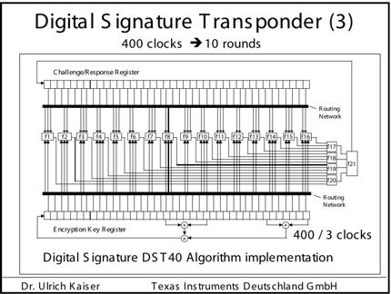
Security Analysis of a Cryptographically-Enabled RFID Device Stephen C. Bono - The Johns Hopkins University Matthew Green - The Johns Hopkins University Adam Stubblefield - The Johns Hopkins University Ari Juels - RSA Laboratories Aviel D. Rubin - The Johns Hopkins University Michael Szydlo - RSA Laboratories Abstract: We describe our success in defeating the security of an RFID device known as a Digital Signature Transponder (DST). Manufactured by Texas Instruments, DST (and variant) devices help secure millions of SpeedPassTM payment transponders and automobile ignition keys. Our analysis of the DST involved three phases: 1 Reverse engineering: Starting from a rough published schematic, we determined the complete functional details of the cipher underpinning the challenge-response protocol in the DST. We accomplished this with only ``oracle'' or ``black-box'' access to an ordinary DST, that is, by experimental observation of responses output by the device. 2 Key cracking: The key length for the DST is only 40 bits. With an array of of sixteen FPGAs operating in parallel, we can recover a DST key in under an hour using two responses to arbitrary challenges. 3 Simulation: Given the key (and serial number) of a DST, we are able to simulate its RF output so as to spoof a reader. As validation of our results, we purchased gasoline at a service station and started an automobile using simulated DST devices. We accomplished all of these steps using inexpensive off-the-shelf equipment, and with minimal RF expertise. This suggests that an attacker with modest resources can emulate a target DST after brief short-range scanning or long-range eavesdropping across several authentication sessions. We conclude that the cryptographic protection afforded by the DST device is relatively weak. Key words: Digital Signature Transponder (DST), immobilizer, Hellman time-space tradeoff, RFID Introduction Radio-Frequency IDentification (RFID) is a general term for small, wireless devices that emit unique identifiers upon interrogation by RFID readers. Ambitious deployment plans by Wal-mart and other large organizations over the next couple of years have prompted intense commercial and scientific interest in RFID [23]. The form of RFID device likely to see the broadest use, particularly in commercial supply chains, is known as an EPC (Electronic Product Code) tag. This is the RFID device specified in the Class 1 Generation 2 standard recently ratified by a major industry consortium known as EPCglobal [9,19]. EPC tags are designed to be very inexpensive - and may soon be available for as little as five cents/unit in large quantities according to some projections [21,20]. They are sometimes viewed in effect as wireless barcodes: They aim to provide identification, but not digital authentication. Indeed, a basic EPC tag lacks sufficient circuitry to implement even symmetric-key cryptographic primitives [21]. The term RFID, however, denotes not just EPC tags, but a spectrum of wireless devices of varying capabilities. More sophisticated and expensive RFID devices can offer cryptographic functionality and therefore support authentication protocols. One of the most popular of such devices is known as a Digital Signature Transponder (DST). Manufactured by Texas Instruments, DSTs are deployed in several applications that are notable for wide-scale deployment and the high costs (financial and otherwise) of a large-scale security breach. These include: • Vehicle Immobilizers: More than 150 million vehicle immobilizer keys shipped with many current automobiles, including e.g. 2005 model Fords [7], use Texas Instruments low-frequency RFID transponders. This number includes systems with fixed-code transponders that provide no cryptographic security, as well as newer models equipped with DSTs. Immobilizers deter vehicle theft by interrogating an RFID transponder embedded in the ignition key as a condition of enabling the fuel-injection system of the vehicle. The devices have been credited with significant reductions in auto theft rates, as much as 90% [1,8]. • Electronic Payment: DSTs are used in the ExxonMobil SpeedPassTM system, with more than seven million cryptographically-enabled keychain tags accepted at 10,000 locations worldwide [2]. A DST consists of a small microchip and antenna coil encapsulated in a plastic or glass capsule. It is a passive device, which is to say that it does not contain an on-board source of power, but rather receives its power via electromagnetic inductance from the interrogation signal transmitted by the reading device. This design choice allows for a compact design and long transponder life. A DST contains a secret, 40-bit cryptographic key that is field-programmable via RF command. In its interaction with a reader, a DST emits a factory-set (24-bit) identifier, and then authenticates itself by engaging in a challenge-response protocol. The reader initiates the protocol by transmitting a 40-bit challenge. The DST encrypts this challenge under its key and, truncating the resulting ciphertext, returns a 24-bit response. It is thus the secrecy of the key that ultimately protects the DST against cloning and simulation. In this paper, we describe our success in attacking the Texas Instruments DST system. We are able to recover the secret cryptographic key from a target DST device after harvesting just two challenge-response pairs. For arbitrary challenge-response pairs, we are able to recover a key in under an hour using an array of sixteen FPGAs. When the challenge-response pairs derive from pre-determined challenges, i.e., in a chosen-plaintext attack, a time-space trade-off is possible, reducing the cracking time to a matter of minutes. The full details of this chosen-response attack will appear in a future version of this work. Once we have recovered a key, we are able to use an inexpensive, commodity RF device to ``clone'' the target DST, that is, to simulate its radio output so as to convince a reader. In consequence, we show how an attacker with modest resources -- just a few hundred dollars worth of commodity equipment and a PC -- can defeat the DST system. Such an attacker can succeed upon actively skimming a DST, that is, scanning it at short range for a fraction of a second. With additional use of an FPGA, an attacker can feasibly simulate a target DST after merely intercepting multiple authentication transcripts at longer range. To validate our attack, we extracted the key from our own SpeedPassTM token and simulated it in an independent programmable RF device. We purchased gasoline successfully at an ExxonMobil station multiple times in the course of a single day using this digital simulator. Similarly, we recovered the cryptographic key from a DST in the ignition key of our 2005 model Ford Escape SUV. By simulating the DST, we spoofed the immobilizer authentication system and started the vehicle with a bare ignition key, that is, a copy of the metal portion of the key that possessed no DST. Viewed another way, we created the pre-conditions for hot-wiring the vehicle. Our aim in demonstrating the vulnerability of the TI DST is twofold. First, we wish to reinforce the time-worn but oft neglected message that ``security through obscurity'' is generally ineffective in widely fielded cryptographic systems. Second, we wish to provide guidance to the data-security community in ascertaining the design requirements for secure RFID systems. Our attack involved three phases: 1 Reverse engineering: We obtained a rough published schematic of the block cipher underpinning the challenge-response protocol in the DST [14]. From this starting point, we determined the complete functional details of the cipher. We accomplished this with only ``oracle'' or ``black-box'' access to an ordinary DST, that is, by experimental observation of responses output by the device across selected programmed encryption keys and selected input challenges. This phase of the attack was the scientific heart of our endeavor, and involved the development of cryptanalytic techniques designed specially for the DST cipher. 2 Key cracking: As mentioned above, the key length for the DST is only 40 bits. We assembled an array of sixteen FPGAs operating in parallel. With this system, we can recover a DST key in under an hour from two responses to arbitrary challenges. Additionally, we have constructed an FPGA for computing the well known time-space tradeoff of Hellman [12]. Although we pre-compute the underlying look-up tables using the FPGA (Field-Programmable Gate Array), we estimate that the resulting software will operate on an ordinary, unenhanced PC in under a minute. (With the aid of an FPGA at this stage, the cracking time can be reduced to seconds.) A full analysis of this system will appear in a future version of this work. 3 Simulation: Given the key (and serial number) of a DST, we are able to simulate its RF output so as to spoof a reader. We perform the simulation in a software radio. Construction of this system required careful analysis of the RF output of the DST reader devices, which differed between SpeedPassTM readers and the automobile ignition system we examined. Related work The pre-eminent historical example of black-box reverse-engineering of a cipher was the reconstruction of the Japanese Foreign Office cipher Purple during the Second World War. Under the leadership of William F. Friedman, the United States Signals Intelligence Service performed the feat of duplicating the Purple enciphering machine without ever having physical access to one [13]. There are a number of well known contemporary examples of the reverse-engineering of proprietary cryptographic algorithms. For example, the RC4 cipher, formerly protected as a trade secret by RSA Data Security Inc., was publicly leaked in 1994 as the result of what was believed to be reverse-engineering of software implementations [4]. The A5/1 and A5/2 ciphers, employed for confidentiality in GSM phones, were likewise publicly disclosed as a result of reverse engineering. The exact method of reverse-engineering has not been disclosed, although the source was purportedly ``an actual GSM phone'' [6]. There are also numerous published fault-induction and side-channel attacks against hardware devices, e.g., [5]. These are related to our work, but involve rather different techniques, and generally aim to recover a key, rather than a cipher design. In fact, we are unaware of any published black-box reverse-engineering of a contemporary cipher, whether the original source be a software or a hardware implementation. Having no literature to refer to, we developed techniques for our effort in an ad hoc manner. While our techniques are not easily generalizable, we hope that they will nonetheless aid future researchers at a conceptual level in similar endeavors. In contrast, the key-recovery techniques we employed are well known. Our parallel FPGA key-recovery system operates on much the same principle, for example, as the well publicized Deep Crack machine that employed hardware-based key-space searching to recover DES keys [10,17]. As mentioned above, our system for key recovery in software using chosen-challenge pairs exploits the time-space tradeoff developed by Hellman. We also employ the ``distinguished point'' enhancement of Rivest. We have drawn on previous work by Quisquater et al. [18], who created a Hellman-based system for recovering keys from a variant of DES employing 40-bit keys. We note that we have chosen in this document to reveal information about the DST cipher sufficient to elucidate our reverse-engineering and analysis techniques. We omit details about that would permit direct reconstruction of the cipher. Our goal is to offer our fullest possible contribution to the scientific community, but at the same time to avoid fomenting abuse of our results. Once the industry has had time to take adequate measures, we intend to divulge full cipher details in the interest of stimulating cryptanalytic research by the scientific community. In general, the problem of achieving authentication in RFID devices - with and without full-blown cryptography - has seen a recent burgeoning in the data-security literature. An up-to-date bibliography may be found at [3]. Organization In section 2, we discuss the practical implications of our simulation attack against the DST. We then detail the three phases of our attack. In section 3, we discuss the techniques we employed in reverse-engineering the DST cipher. We describe our key-cracking system in section 4. In section 5, we recount the experimentation and analysis we performed to understand the DST protocol at the RF layer, as well as our simulation techniques. We conclude in section 6. Practical Significance of Our Results Our attack on the DST cipher by no means implies wholesale dismantling of the security of the SpeedPassTM network, nor easy theft of automobiles. The cryptographic challenge-response protocols of DST devices constitute only one of several layers of security in these systems. ExxonMobil informed us that the SpeedPassTM network has on-line fraud detection mechanisms loosely analogous to those employed for traditional credit-card transaction processing. Thus an attacker that simulates a target DST cannot do so with complete impunity; suspicious usage patterns may result in flagging and disabling of a SpeedPassTM device in the network. The most serious system-wide threat lies in the ability of an attacker to target and simulate multiple DSTs, as suggested in our example scenarios below. In some sense, the threat to automobile immobilizers is more serious, as: (1) An automobile is effectively an off-line security system and (2) A single successful attack on an automobile immobilizer can result in full compromise of the vehicle. While compromise of a DST does not immediately permit theft of an automobile, it renders an automobile with an immobilizer as vulnerable to theft as an automobile without one. Such a rollback in automobile security has serious implications. As noted above, significant declines in automobile theft rates - up to 90% - have been attributed to immobilizers during their initial introduction. Even now, automobile theft is an enormous criminal industry, with 1,260,471 automobile thefts registered by the FBI in 2003 in the United States alone, for a total estimated loss of $8.6 billion [16]. Extracting the key from a DST device requires the harvesting of two challenge-response pairs. As a result, there are certain physical obstacles to successful attack. Nonetheless, bypassing the cryptographic protections in DST devices results in considerably elevated real-world threats. In this section we elaborate on the context and implications of our work. Effective attack range There are effectively two different methods by which an attacker may harvest signals from a target DST, and two different corresponding physical ranges. The first mode of attack is active scanning: The attacker brings her own reader within scanning range of the target DST. DSTs of the type found in SpeedPassTM and automobile ignition keys are designed for short range scanning - on the order of a few centimeters. In practice, however, a longer range is achievable. In preliminary experiments, we have achieved an effective range of several inches for a DST on a keyring in the pocket of a simulated victim. A DST may respond to as many as eight queries per second. Thus, it is possible to perform the two scans requisite for our simulation attacks in as little as one-quarter of a second. At the limit of the range achievable by a given antenna, however, scanning becomes somewhat unreliable, and can require more time. From the standpoint of an attacker, active scanning has the advantage of permitting a chosen-challenge attack. Hence this type of attack permits the use of pre-computed Hellman tables as touched on above. In principle, therefore, it would be possible for an attacker with appropriate engineering expertise to construct a completely self-contained cloning device about the size of an Apple iPod. When passed in close proximity to a target DST, this device would harvest two chosen-challenge transcripts, perform a lookup in an on-board set of pre-computed Hellman tables in the course of a minute or so, and then simulate the target DST. We estimate that the cost of constructing such a device would be on the order of several hundred dollars. The second mode of attack is passive eavesdropping. Limitations on the effective range of active scanning stem from the requirement that a reader antenna furnish power to the target DST. An attacker might instead eavesdrop on the communication between a legitimate reader and a target DST during a valid authentication session. In this case, the attacker need not furnish power to the DST. The effective eavesdropping range then depends solely on the ability to intercept the signal emitted by the DST. We have not performed any experiments to determine the range at which this attack might be mounted. It is worth noting purported U.S. Department of Homeland Security reports, however, of successful eavesdropping of this kind on 13.56 Mhz tags at a distance of some tens of feet [24]. The DST, as we explain below, operates at 134 kHz. Signals at this considerably lower frequency penetrate obstacles more effectively, which may facilitate eavesdropping. On the other hand, larger antennas are required for effective signal interception. Only careful experimentation will permit accurate assessment of the degree of these two threats. Our cursory experiments, however, suggest that the threats are well within the realm of practical execution. Example attack scenarios For further clarification of the implications of our work, we offer a few examples of possible DST exploits. We let Eve represent the malefactor in these scenarios. Example 1 (Auto theft via eavesdropping) Eve runs an automobile theft ring. She owns a van with eavesdropping equipment. She parks this near a target automobile so as to eavesdrop on ignition-key-to-reader transmissions.4 After observing two turns of the ignition key, she is able to extract the cryptographic key of the DST at her leisure using an FPGA. She returns subsequently to steal the target automobile. To enter the vehicle, she picks or jimmies the door lock. She then hot-wires the ignition and deactivates the immobilizer by simulating the DST of the real key. Example 2 (Auto theft via active attack) Eve runs an automobile theft ring. She suborns a valet at an expensive restaurant to scan the immobilizer keys of patrons while parking their cars, and to note their registration numbers. Based on these registration numbers, Eve looks up the addresses of her victims (such background checks being widely offered on the Internet). By simulating their DST devices, Eve is able to steal their automobiles from their homes. Example 3 (SpeedPassTM theft via active attack) Eve carries a reader and short-range antenna with her onto a subway car. (Alternatively, Eve could carry a large ``package'' with a concealed antenna in some public place.) As she brushes up near other passengers, she harvests chosen challenge-response pairs (along with the serial numbers of target devices) from any SpeedPassTM tokens they may be carrying. Later, at her leisure, Eve recovers the associated cryptographic keys. She programs the keys into a software radio, which she uses to purchase gasoline. To allay suspicion, she takes care to simulate a compromised SpeedPassTM only once. Additionally, she hides the tag simulator itself under her clothing, interacting with the pump reader via an antenna passing through a sleeve up to an inactive SpeedPassTM casing. Fixes The most straightforward architectural fix to the problems we describe here is simple: The underlying cryptography should be based on a standard, publicly scrutinized algorithm with an adequate key length, e.g., the Advanced Encryption Standard (AES) in its 128-bit form, or more appropriately for this application, HMAC-SHA1 [15]. From a commercial standpoint, this approach may be problematic in two respects. First, the required circuitry would result in a substantially increased manufacturing cost, and might have other impacts on the overall system architecture due to increased power consumption. Second, there is the problem of backwards compatability. It would be expensive to replace all existing DST-based immobilizer keys. Indeed, given the long production cycles for automobiles, it might be difficult to introduce a new cipher into the immobilizers of a particular make of vehicle for a matter of years. On the other hand, it may be presumed from the Kaiser presentation [14] that Texas Instruments has plans to update their cipher designs in the DST. Additionally, TI has indicated to the authors that they have more secure RFID products available at present; in lieu of specifying these products, they have indicated the site www.ti-rfid.com for information. In fact, RFID chips with somewhat longer key-lengths are already available in the marketplace and used in a range of automobile immobilizers. Philips offers two cryptographically enabled RFID chips for immobilizers [8]. The Philips HITAG 2, however, has a 48-bit secret key, and thus offers only marginally better resistance to a brute-force attack - certainly not a comfortable level for long-term security. The Philips SECT, in contrast, has a 128-bit key. The HITAG 2 algorithm is proprietary, while Philips data sheets do not appear to offer information about the cryptographic algorithm underpinning their SECT device. Thus, at present, we cannot say whether these algorithms are well designed. Faraday shielding offers a short-term, partial remedy. In particular, users may encase their DSTs in aluminum foil or some suitable radio-reflective shielding when not using them. This would defend against active scanning attacks, but not against passive eavesdropping. Moreover, this approach is rather inconvenient, and would probably prove an unworkable imposition on most users. A different measure worth investigation is the placement of metal shielding in the form of a partial cylinder around the ignition-key slot in automobiles. This could have the effect of attenuating the effective eavesdropping range. In the long-term, the best approach is, of course, the development of solid, well-modeled cryptographic protocols predicated on industry-standard algorithms, with key lengths suitable for long-term hardware deployment. Reverse Engineering We now present the details of our attack. The 40-bit cipher underpinning the DST system is proprietary. We refer to this cipher, in accordance with the Texas Instruments documentation, as DST Figure 1: Schematic of Kaiser Cipher.
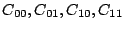
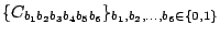
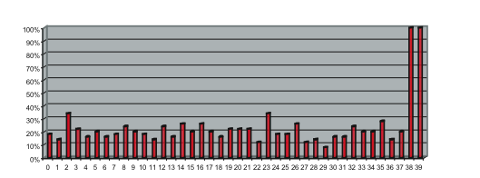
We considered several initial approaches to reverse-engineering DST To explain our effort further, some nomenclature is in order. As the TI schematic of the Kaiser cipher suggests, DST The first layer, represented in the schematic by boxes The second layer, represented in the schematic by boxes Finally, the third layer consists of a single functional unit, labeled There are two main technical lacunae in the TI schematic. Reverse-engineering DST 1 The schematic does not describe the logical operations executed by the 2 The mapping of key and challenge bits to the In addition, as we shall explain, the TI schematic contains some inaccuracies, in the sense that the Kaiser cipher does not correspond exactly to DST Obtaining a single-round output Because we did not know the contents of the We first noted that the only round dependence of the Kaiser cipher is in the key scheduler. As seen in Figure 1, a We next observed that each cycle, i.e., each execution of Using the DST as an oracle, we developed a test to recover the output of the Fortunately, access to the DST as a challenge/response oracle offers a simple way to make this determination. If Based on the assumption that the encryption circuitry in a production DST tag implements the algorithm of Figure 1, we performed this test using an evaluation DST purchased from Texas Instruments. First, we programmed the DST with the Unfortunately, this test failed to produce the results we expected, indicating that DST Through trial and error, we discovered that the method of testing next-state challenge-register values succeeded when we modeled the output of the With the ability to recover the output of Recovering the key schedule Our experiments, as described above, relied on the assumption that the Using a non-zero key again made the algorithm round-dependent, with the result that our previous tests would no longer produce useful results. In order for our ``next-state'' candidate challenges to be encrypted properly, we needed to provide the oracle with the equivalent next-state of the key register. Our next step, therefore, was to reverse-engineer the key schedule. Following the diagram, we assumed that new key bits were computed every few cycles by the exclusive-or of several bits of the key. By querying our oracle, we determined that the key is updated every three cycles, beginning with the second cycle - not the first, as suggested by the Kaiser diagram. We also determined that while four bits are indeed exclusive-ored together, they are not the bits shown in the diagram. Let With the Uncovering the Feistel structure of DST Figure 2 shows the probability that modifying an individual challenge bit results in a change to the output of Figure 2: Frequency of change in single round output value on flipping of individual challenge bits.
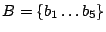
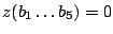
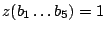
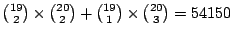
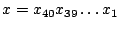
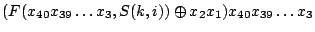
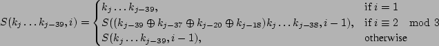
Let The XOR effect of bits For the DST, the choice of a Feistal cipher is not a necessary choice, although a useful one. We speculate that the round function was chosen to be a permutation, so that the effect of collisions would not multiply, and the responses would have a uniform distribution. Recovering the bit routing networks After identifying the general structure of the cipher, our next step was to uncover the internal routing network of bits, i.e., which bits act as inputs to each of the The structure of the Kaiser cipher is such that Using this simple but powerful observation, we devised a test to determine which groups of input bits from the challenge and key are routed into each of the four We employed this test first so as to exclude all bits that are not in the same A slightly more complicated task lay in determining the routing network for DST A given In contrast, suppose that Using our invariant, we can perform a test to exclude combinations of bits that cannot be inputs to the same On first inspection, it would appear as though there is a large number of possible sets of input bits to any given Furthermore, again to our benefit, the Building logical tables for the Once we identified the bits corresponding to each Given this knowledge, we proceeded to construction of the Refer to Appendix A for the full DST Key Cracking We were able to verify that our reverse engineering of the DST We also wished to test our implementation against actual fielded tags in SpeedPassTM tokens and automobile ignition keys. The cryptographic keys in these devices are immutable once locked at the factory. Without knowing the key on a fielded tag, we had no way to determine whether the algorithm used by such tags was as hypothesized. Therefore, recovering an actual key became necessary. The DST We first coded our hypothesized DST40 in software. It quickly became clear that this implementation was not sufficiently fast for use in a keycracker: Even after hand-optimization, our software computed fewer than 200,000 encryptions per second on a 3.4 GHz Pentium workstation. At this rate it would take over two weeks for a cluster of ten computers to crack a single key. We instead chose to implement the keycracker in hardware. Each node of our cracker consists of a single Xilinx XC3S1000 FPGA on a commercial evaluation board, available for under $200 in single quantities. In our VHDL implementation, each DST In addition to the FPGA, each evaluation board contains switches, LEDs, support chips, and a variety of connectors. We chose to connect a PS/2 keyboard to the FPGAs to provide the inputs (the challenge/response pairs) while the outputs (the key) appeared on the LEDs. Because the DST A single board was sufficient to verify that our reverse engineering was correct with respect to fielded DST tags. In just under 11 hours the cracker recovered the key from a SpeedPassTM which we used to compute new responses that matched those from the tag. While 11 hours of computation is perfectly reasonable in many attack scenarios, we decided to engineer a cracker that a modestly funded adversary could use to recover keys in under an hour. By purchasing 16 evaluation boards at a cost of under $3500, and connecting the boards together with flat wire connectors, we were able to create a parallel version of our already parallel single-chip cracker. The parallel cracker still allows a user to input the desired search points using a single keyboard; the information is then passed via a flat wire connector from board to board. The portion of the key-space that each board is responsible for is set using four switches and, when found, the key is displayed on the LEDs. To assist us in validating our results, Texas Instruments provided us with five DST tags and challenged us to recover their keys. Using the parallel cracker, we were able to crack all five keys in under two hours. That this is shorter than the expected time for five keys can be explained by the lack of any hex digit above 9 in any of the five keys. While it appears that these keys were not chosen at random (and indeed were probably entered by hand), the actual keys in deployed DST devices do seem to be randomly distributed. The Hellman time-space tradeoff As explained above, we have constructed a software key cracker that uses Hellman tables based on the parameters set forth in the work by Quisquater et al. While table building is not yet complete, rough estimates suggest that a key-cracking program capable of a success rate of 99+% should require about 10 GB of storage, and should operate in under a minute on a fast PC. Construction of the tables requires considerable pre-computation. At the time of writing of this paper, we are in the process of table building and hope soon to report results of this work. RF Protocol Analysis and Simulation Low-frequency RFID systems typically make use of powered readers and passive transponders. In the DST system, the reader transmits power to the transponder via a 15-to-50 ms electromagnetic pulse at 134.2 kHz. Once powered, a transponder can receive and respond to commands from the reader, including challenges and read and write operations. The transponder can also execute computations, including as cryptographic operations. A reader transmits commands as a sequence of amplitude-modulated (AM) bits. Once a power burst has ended, the reader signal will drop significantly in amplitude for some period of time. It is the duration of this ``off-time'' that communicates a bit value to the transponder. A short off-time duration specifies a `0' bit, while a longer duration specifies a `1' bit. Between each bit transmission, the reader signals returns to full amplitude in order to delimit the off-time intervals and maintain the powered state of the transponder. In some cases, after sending a command to a transponder, a reader will transmit a short, supplementary power burst to energize the tag fully. Once the transponder has fully received and processed a command, it discharges its stored power, while transmitting its response using frequency modulated frequency shift keying (FM-FSK). It communicates a bit via 16 RF cycles, specifying a `0' or `1' bit by transmitting at 134.2 kHz or 123.2 kHz respectively.8 A preamble of `0' bits followed by a start byte (7E hex) indicates the start of a transmission and allows the reader to synchronize. Sniffing the protocol Given an understanding of the communication medium between reader and transponder, eavesdropping on or creating protocol transmissions is a matter of having the right equipment and software applications. With this aim, we have equipped a small and easily portable PC with a Measurement Computing digital-to-analog conversion (DAC) board. This board is also capable of analog-to-digital conversion. The DAC board can perform 12-bit A/D conversions on an input signal at a rate of 1.25 MHz, and can perform D/A conversions and generate an output signal at a rate of 1 MHz. These rates are quite sufficient for our purposes. In our work with DSTs, we are manipulating signals with frequencies approximately 1/7th the maximum input and output rates of the DAC. We connected the input and output channels on our DAC board to an antenna tuned to the 134 kHz range. The particular antenna we used in our experiments comes with TI's micro-reader evaluation kit, and is thus designed to receive and transmit analog signals within our desired frequency range. We wrote modulation and demodulation software routines to decode and produce the analog AM signals transmitted by the TI reader, as well as FM-FSK analog signals transmitted by DST transponders. Using these routines, our equipment can eavesdrop on the communication protocol between a DST reader and transponder, or participate actively in a protocol by emulating either device. Putting together the pieces: the full DST protocol As explained above, the DST protocol hinges on a relatively straightforward challenge-response protocol. The reader first transmits a challenge request to a transponder, consisting of an 8-bit opcode followed by a 40-bit challenge. The opcode indicates the type of request being made (in this case an authentication request). As noted above, the transponder encrypts the challenge using the secret 40-bit key it shares with the reader; the resulting least significant 24 bits in the transponder challenge register constitutes a 24-bit signature. The transponder replies to the reader with its 24-bit serial number, the 24-bit signature and lastly a keyed 16-bit CRC of the data being transmitted. Using the shared encryption key (which it may look up based on the transponder serial number) and secret CRC start value, the reader can verify that the signature is correct. The CRC appended to each transmission is intended to be an additional security measure as well as an error checking device. The DST protocol specification defines this as a 16-bit reverse CRC-CCITT that is initialized with a secret 16-bit start value. However, this feature provides no such security. A single interaction with a DST allows for the recovery of a transmission and accompanying keyed CRC. As this secret start value is shared among all DSTs, it is only a matter of trying the Therefore, the security of authentication in this system depends on the supposition that the 40-bit secret key contained in a valid transponder is available only to the transponder and to valid readers, and that only knowledge of this shared secret allows the correct generation of a signature. The system architects specified as a design criterion that having access to a transponder or reader for short periods of time should not lead to recovery of the secret key [11]. Their stated aim was to make the DST system resistant to signature-guessing attacks, dictionary attacks using known challenge-response pairs, cryptanalytic attacks, and exhaustive key search - even for an attacker with full knowledge of the encryption algorithm. Simulating a DST device Given the secret 40-bit key for a DST, simulation is a simple matter: In the presence of a valid reader, we emulate the participation of the target DST in an authentication protocol using a software radio. In particular, our software performs the following steps: (1) It analyzes the A/D conversions received from the DAC board, (2) Decodes the AM signal containing the challenge sent from the reader, (3) Performs an encryption of this challenge using the recovered secret DST key, (4) Codes the FM-FSK signal representing the correct response, and (5) Outputs this FM-FSK signal to the DAC board. Of course, enhancing the software to implement any operation in the DST-protocol variants is a straightforward matter. Conclusion The weakness we have demonstrated in the TI system is ultimately due to the inadequate key-length of the underlying DST The authors hope that future cryptographic RFID system designers will embrace a critical lesson preached by the scientific community: Cryptographic hardware systems are generally strongest when they employ industry standard cryptographic algorithms with key lengths sufficient to endure over the life of the devices and assets they protect. Acknowledgments Thanks to Dan Bailey, Cindy Cohn, Ed Felten, Kevin Fu, Ron Juels, Burt Kaliski, Kurt Opsahl, Ron Rivest, Marian Titerence, and David Wagner for their valuable suggestions and comments and their support of this work. We also thank Texas Instruments for their cooperation after we disclosed our results to them and for feedback on earlier drafts of this paper. Notes 4 Note that although the metal panels of the automobile act as a Faraday cage, the low frequency of the DST signal may effectively penetrate the windows. This is a matter of speculation at present. ... bits. 5 Occasionally this experiment produces multiple candidates that generate a matching response. Some collisions are inevitable in an algorithm with a larger input than output size. 6 We cannot tell whether a particular output value for ... ones. 7 We might instead have tested the hypothesis that 8 The TI documentation indicates slightly different frequencies for different devices. The TI glass transponder transmits at 134.3 and 122.9 kHz, while the wedge-shaped transponder transmits at 134.5 and 123.7 kHz. Bibliography 1 Automotive immobilizer anti-theft systems experience rapid growth in 1999, 1 June 1999. Texas Instruments Press Release. Available at https://www.ti.com/tiris/docs/news/news_releases/ 90s/rel06-01-99.shtml. 2 SpeedpassTM Press Kit Fact Sheet, June 2004. Referenced at https://www.exxonmobil.com/corporate/files/ corporate/speedpass_fact_sheet.pdf. 3 Security and privacy in rfid systems, 2005. Web-based bibliography. Referenced at https://lasecwww.epfl.ch/gavoine/rfid/. 4 AN0NYM0US USER. RC4?, September 1994. Sci.crypt posting. 5 BIHAM, E., AND SHAMIR, A. Differential fault analysis of secret key cryptosystems. In CRYPTO '97 (1997), B. Kaliski, Ed., Springer-Verlag, pp. 513-525. 6 BIRYUKOV, A., SHAMIR, A., AND WAGNER, D. Real time cryptanalysis of A5/1 on a PC. In Fast Software Encryption (FSE) (2000), pp. 1 - 18. 7 BOURQUE, D. Technology update, chip status and development, October 2004. Slide presentation. Referenced at https://www.ris.averydennison.com/ris/ris2site.nsf/ (Image)/Texas_Instruments_(Eng.)/ $File/Texas%20Instruments%20(Eng.).pdf. 8 ELECTRONICS, R. P. Identification applications - car immobilization, 2005. Web page. Referenced at https://www.semiconductors.philips.com/markets/ identification/products/automotive/transponders/ Contains links to data sheets. 9 EPCglobal Web site. https://www.epcglobalinc.org, 2005. 10 GILMORE, J. EFF builds DES cracker that proves that data encryption standard is insecure. EFF press release (July 1998). 11 GORDON, J., KAISER, U., AND SABETTI, T. A low cost transponder for high security vehicle immobilizers. In 29th ISATA Automotive Symposium (3-6 June 1996). 12 HELLMAN, M. A cryptanalytic time-memory trade-off. IEEE Transactions on Information Theory 26, 4 (July 1980), 410-416. 13 KAHN, D. The Codebreakers: The Comprehensive History of Secret Communication from Ancient Times to the Internet. Macmillan, 1996. 14 KAISER, U. Universal immobilizer crypto engine. In Fourth Conference on the Advanced Encryption Standard (AES) (2004). Guest presentation. Slides referenced at https://www.aes4.org/english/events/aes4/ program.html. 15 KRAWCZYK, H., BELLARE, M., AND CANETTI, R. HMAC: Keyed-hashing for message authentication. Internet Request For Comments (RFC) 2104 (February 1997). 16 OF INVESTIGATION (FBI), F. B. Uniform crime report, 2003. Referenced at https://www.fbi.gov/ucr/03cius.htm. 17 QUISQUATER, J., AND STANDAERT, F. Exhaustive key search of the DES: Updates and refinements. SHARCS 2005 (2005). 18 QUISQUATER, J.-J., STANDAERT, F.-X., ROUVROY, G., DAVID, J.-P., AND LEGAT, J.-D. A cryptanalytic time-memory tradeoff: First FPGA implementation, 2002. 19 ROBERTI, M. EPCglobal ratifies Gen 2 standard. RFID Journal (16 Dec. 2004). Referenced at https://www.rfidjournal.com/article/articleview/ 1293/1/1/. 20 SARMA, S. Towards the five-cent tag. Tech. Rep. MIT-AUTOID-WH-006, MIT Auto ID Center, 2001. Referenced at https://www.epcglobalinc.org. 21 SARMA, S. E., WEIS, S. A., AND ENGELS, D. Radio-frequency-identification security risks and challenges. rsa laboratories. CryptoBytes 6, 1 (2003). 22 SCHNEIER, B., AND KELSEY, J. Unbalanced feistel networks and block cipher design. In Fast Software Encryption (FSE) (1996), p. 121—144. 23 SULLIVAN, L. Wal-Mart oulines RFID expansion plans. InformationWeek (17 June 2004). 24 YOSHIDA, J. Tests reveal e-passport security flaw. EE Times (30 August 2004). Referenced at https://www.eedesign.com/news/ showArticle.jhtml?articleID=45400010. Appendix A - The Full DST To facilitate further analysis of the DST where The key schedule, Figure 3: The key scheduler,
Figure 4: The structure of the boolean function,
Figure 5: The
About this document ... Security Analysis of a Cryptographically-Enabled RFID Device This document was generated using the LaTeX2HTML translator Version 2002-2-1 (1.70) Copyright © 1993, 1994, 1995, 1996, Nikos Drakos, Computer Based Learning Unit, University of Leeds. Copyright © 1997, 1998, 1999, Ross Moore, Mathematics Department, Macquarie University, Sydney. |
|
This paper was originally published in the
Proceedings of the 14th USENIX Security Symposium,
July 31–August 5, 2005, Baltimore, MD Last changed: 3 Aug. 2005 ch |
|