To remedy this problem, we propose Softspeak, a pair of backwards-compatible software extensions that enables VoIP traffic to share the channel in a more efficient, TDMA-like manner. Softspeak does not require any modifications to the WiFi protocols and significantly reduces the impact of VoIP on TCP capacity while simultaneously improving key VoIP call-quality metrics. Results show improvements in TCP download capacity of 380% for 802.11b and 25-200% for 802.11g.
One might imagine that such a scenario would be easily supported by existing installations, as VoIP is a relatively low-bandwidth protocol. For example, given an 802.11b channel with 11 Mbps of capacity, a G.7291 VoIP codec rate of 6.4 Kbps, and a combined header size of RTP, UDP and IP of 40 bytes, one might expect a single AP to support over 70 bidirectional VoIP calls and still leave half of the channel capacity for data traffic. It is well known, however, that nothing could be further from the truth; previous researchers have shown that an 802.11b network supports as few as six simultaneous VoIP sessions [4,9,20], depending upon the particular characteristics of the network and codecs in use. This counterintuitive result is due to the large per-packet overhead imposed by WiFi for each VoIP packet-both in terms of protocol headers and due to WiFi contention.
Call quality has traditionally been a major concern for WiFi VoIP deployments, since real-time audio traffic has stringent requirements in terms of loss rate, delay and jitter, and needs to be sent at a high rate (e.g., 50-100 packets per second for many VoIP codecs) to maintain acceptable audio quality. In mixed-use cases, best-effort traffic can cause excessive queuing of VoIP traffic at access points and may increase packet loss rate due to contention for the medium. Since a VoIP call occupies only a very small amount of bandwidth (possibly as few as eight bytes of voice data per packet), many researchers [4,25] and commercial providers [2] have proposed prioritizing VoIP packets, with the unstated assumption that the impact on overall network performance will be minimal. However, as we demonstrate experimentally, as few as six VoIP calls may remove over half of the TCP capacity in 802.11b. Moreover, prioritizing VoIP sessions runs the very real danger of drowning out all competing best-effort traffic, such as Web browsing and email messaging. Somewhat surprisingly, our experiments show that neither the increased speed of 802.11a/g nor the quality-of-service mechanisms of 802.11e change this reality.
In this paper, we address the impending potential disaster: that widespread VoIP usage will cripple hotspot and enterprise WiFi networks. In addition to quantifying and explaining the impact of VoIP on the capacity of WiFi, we propose backward-compatible modifications to 802.11 that aggregate multiple VoIP clients into the equivalent of a single VoIP client, thus reducing VoIP's impact on the network's data-carrying capacity.
Previous work in this domain has proposed the concept of `downlink aggregation' in simulation [23,24], which encapsulates multiple VoIP packets into a single packet at the AP, addressed to all VoIP stations associated with the same AP. Our experiments demonstrate, however, that downlink aggregation is insufficient to fully address the problem. We present a complementary technique for the uplink direction that serializes channel access by establishing a TDMA-like schedule. We show that this can be done in a distributed manner by independent VoIP stations. We combine uplink TDMA and downlink aggregation mechanisms to develop a system called Softspeak that simultaneously improves VoIP call quality while preserving network capacity for best-effort data transfer.
We implement and evaluate Softspeak on a testbed of Linux-based 802.11b/g/e devices within an operational enterprise WiFi network. We show that Softspeak improves residual downlink TCP capacity of the network substantially, e.g., by 380% in the presence of ten VoIP calls in 802.11b and by 200% in 802.11g (protected mode). We also achieve significant improvements in UDP and TCP uplink capacity, as well as in 802.11g unprotected mode. Furthermore, we show that Softspeak can improve VoIP call quality, providing an important incentive for client deployment. To the best of our knowledge, our work is the first to present a system based on commodity hardware that performs both uplink TDMA and downlink aggregation to improve the performance of multiple, simultaneous VoIP sessions while increasing the residual data-carrying capacity of the WiFi network.
Furthermore, given the small data payload of VoIP packets the overhead of transmitting the various headers in a VoIP packet becomes considerable: each VoIP packet in a WiFi network is typically encumbered with RTP, UDP, IP, MAC and PHY headers as well as a synchronous 802.11 ACK frame. For example, a G.729 packet may take 157 us to transmit at the maximum rate in 802.11b, or 273 us if we include the ACK frame (and assume it is sent at maximum rate). Of this time, the eight bytes of voice data carried inside the packet take up only six microseconds; the entire IP packet requires only 35 us of airtime, resulting in 680% overhead. Although 802.11g can reduce this overhead to 240% in the best case, the overhead remains substantial at over 400% (again optimistically assuming maximum rates are used) in protected mode, which is required when any legacy 802.11b device is present.
Additionally, airtime usage may increase in response to loss rate, as rate control algorithms frequently lower the transmission rate in response to loss, regardless of whether the loss was due to poor signal quality or frame collision. Finally, we note that the resulting increase in airtime scarcity in turn tends to increase collision probability and loss rate as more stations attempt to seize the channel at once, thereby completing a vicious circle.
We are interested in the residual WiFi capacity as well as VoIP call quality in the presence of a varying number of VoIP stations. Here, we measure the residual capacity by simultaneously running a bulk flow and measuring its throughput. We conduct separate experiments for uplink and downlink bulk flows, using both TCP and UDP. Our experiments with UDP measure the raw channel capacity available, while TCP measures the effective capacity for flows that are sensitive to loss and delay. For simplicity, we restrict our discussion to experiments using a single non-VoIP flow at a separate client; we present results for multiple data clients in Section 4.5.
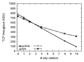
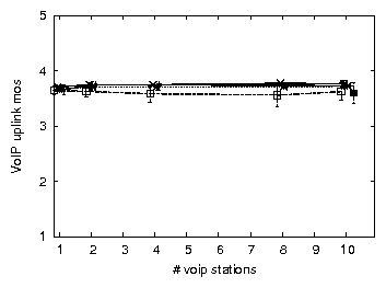
Figure 1 plots the throughput of TCP in the presence of a varying number of VoIP stations in an 802.11b network. As we increase the number of VoIP streams, the throughput of a TCP uplink flow (where "uplink" refers to the direction of the TCP data packets) degrades, halving at around eight VoIP streams. In typical TCP usage (e.g., Web traffic) more throughput is required from the downlink direction than from the uplink direction. Unfortunately, throughput degradation is far worse for a TCP downlink flow, which can be explained as follows. TCP's congestion control mechanism attempts to use the maximum bandwidth available given the loss rate and the RTT. For both cases, the TCP sender needs to share the AP with other traffic for its downlink traffic (data packets for TCP downlink or ACK packets for TCP uplink), and it is therefore at the AP that most losses are expected to occur. Losing a data packet is far worse than losing an ACK packet, however. Therefore, TCP is able to tolerate a higher loss rate at the AP and achieve a higher throughput when sending data uplink. As a result, TCP downlink throughput halves at six VoIP streams and degrades by over 85% in the presence of ten VoIP streams.
UDP throughput degradation is less severe than that of TCP because UDP is less sensitive to loss and delay. Nevertheless we observe a significant throughput degradation (over 55% with ten VoIP sessions). We further note that the behavior of uplink UDP and TCP traffic and their impact on VoIP traffic appears quite similar, indicating that in our testbed the TCP uplink behavior is characterized mostly by channel capacity, rather than by loss and delay.
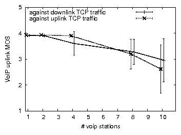
In practice, however, our enterprise WiFi deployment almost never supports only 802.11g clients. For backwards compatibility, 802.11g requires a "protected mode" be used when 802.11b stations are detected. In protected mode an 802.11g station precedes each transmission by a clear-to-send (CTS) frame, thus increasing per-frame overhead. We observe that the capacity degradation caused by 802.11g VoIP clients in an 802.11g protected-mode network is comparable to that of native 802.11b. Thus, the presence of a single legacy 802.11b client (VoIP or otherwise) alongside ten VoIP clients removes 87% of TCP downlink capacity. In addition, we find that whereas VoIP uplink loss is negligible in 802.11b in the presence of TCP downlink traffic, it varies from 10-40% in 802.11g protected mode, resulting in an average VoIP MOS value of 2.0.
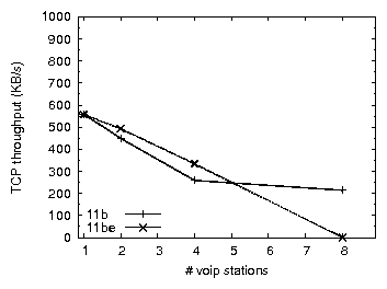
The 802.11e protocol is specifically designed to allow real-time and data traffic to co-exist efficiently by prioritizing real-time traffic. We compare the performance of 802.11b and 802.11b+e using a popular 802.11e capable access point (a Linksys WAP4400N, different from the Avaya AP-8 used in the previous experiments, which does not support 802.11e), with VoIP traffic configured to be classified and prioritized over other traffic at both the AP and the clients. In the presence of TCP uplink traffic, we observe that compared to 802.11b, 802.11e does indeed improve the MOS of VoIP traffic. However, as shown in Figure 2, this improvement is achieved at the expense of TCP uplink throughput, which degrades far more severely than is the case for 802.11b. TCP downlink performance is essentially similar to that of 802.11b, with a slight improvement in MOS. We conclude that while 802.11e (at least as implemented by a popular AP vendor) is able to improve call quality in some cases, it does not mitigate throughput degradation in the presence of a large number of VoIP clients.
By combining multiple 10-ms voice frames into a single IP packet, G.729 can be run at longer inter-packet intervals, thereby making more efficient use of network resources. Figure 3 considers a 20-ms G.729 codec in combination with TCP in 802.11g protected mode. As expected, the impact is less than for a 10-ms codec yet remains severe; the MOS for uplink VoIP traffic drops from 4 to 3 on average (compared to 2 in the 10-ms case) and, more importantly, becomes highly erratic. Uplink and downlink TCP throughput reduce by around 40% (not shown, c.f. 87% in the 10-ms case for TCP downlink).
We simulate the 802.11b experiment described earlier for UDP and find that the results are very similar in airtime. For example, simulated throughput degradation is within 10% of the experimental results. The largest difference between the simulated and experimental results is seen in the uplink VoIP loss rate which is 0.8-2.3% for ten VoIP stations versus less than 0.02% on the testbed.
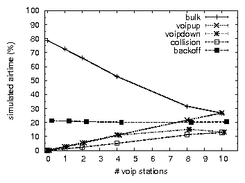
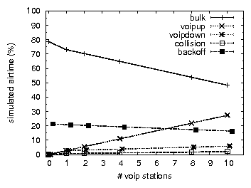
Having established that our simulation exhibits a similar behavior as the testbed in 802.11b, and that a DCF-based model is sufficient to explain the degradation of residual capacity in our testbed under VoIP, we now analyze the simulation data to determine which aspect of DCF causes the observed behavior. Figure 4 shows the simulated airtime used by each of the following components: non-colliding bulk traffic (bulk), non-colliding VoIP uplink and downlink traffic (voipup, voipdown), colliding packets (collisions), and times when all stations are backing off or sensing the medium (backoff).
VoIP takes up a large fraction of the airtime, e.g., 40% for ten sessions, exceeding the airtime used by bulk traffic. Most of the VoIP airtime (35%) consists of framing overhead. Additionally, 33% of total airtime is overhead due to contention (20% backoff plus 13% wasted on collisions). The techniques presented in the next section are capable of reducing a significant portion of overhead, specifically the framing overhead of downlink VoIP traffic (11%) and the collision time (13%). Based upon these numbers alone there is potential to almost double the residual channel capacity.
We remove the VoIP clients from the standard contention process by modifying their backoff behavior. Instead of sensing the medium for the 802.11-mandated DCF inter-frame spacing (DIFS) followed by a random backoff before sending, a Softspeak VoIP client senses for a shorter period of time and does not perform backoff, thus preventing collisions with non-VoIP traffic. (In the absence of hidden terminals, collisions with ACKs are prevented by 802.11's NAV mechanism.) This behavior effectively prioritizes uplink VoIP traffic and improves call quality. (A similar mechanism is employed by a commercial product, SVP [2].) By itself, however, this alteration inhibits DCF's ability to prevent collisions among the VoIP stations. In fact, when we simulate only two VoIP stations that sense for a short inter-frame spacing (SIFS) without backoff in combination with bulk traffic that uses standard contention, we find that neither VoIP station is able to sustain a viable VoIP session.
To prevent VoIP stations from colliding with each other, we introduce coarse-grained time slots and construct a TDMA schedule for the VoIP clients. When used in combination with downlink aggregation, the downlink aggregator node can assign TDMA slots as well as perform admission control, since it has knowledge of all the clients using our scheme. In the absence of a centralized scheduler, we devise a distributed mechanism (Section 3.1.1) that leverages management frames within the 802.11 protocol to allocate slots.
In an ideal deployment, the network operator will have installed a Softspeak VoIP downlink aggregator that can assign slots for uplink TDMA. If all available slots are in use it can deny access to a new Softspeak client, in which case that client resorts to normal 802.11 DCF. In some scenarios, however, it may be easier for individual clients to install Softspeak software than to convince network operators to install new hardware. Moreover, uplink TDMA is useful by itself, i.e., without downlink aggregation, since it reduces contention by uplink VoIP stations. Hence, if clients are unable to locate a VoIP aggregator (Section 3.2 describes the registration process), they proceed with a distributed allocation process.
Independent of how TDMA slots are allocated to clients, VoIP stations need to be synchronized in order to correctly use their assigned slots. Each client uses the periodic beacon frame broadcast by an 802.11 AP to synchronize with other VoIP clients. Beacons are sent at fixed intervals (usually 100 ms), and, since they are sent by the AP at a low bit rate, are typically received by all clients. It is important to note that a VoIP client may also hear beacons from an AP other than the one to which it is associated. To use beacon-based synchronization, VoIP clients need two important pieces of information: a) The AP to whose beacons other nearby VoIP clients are synchronizing, and b) which TDMA slots they are using. The slot allocation process provides both pieces of information. In the case of distributed slot allocation each VoIP client encodes the information by temporarily spoofing its MAC address (6 octets) as follows:
A new VoIP station that wants to use uplink TDMA first enters promiscuous mode for a few seconds to sense the channel to check if there are any special Probe-Response packets (easily identifiable by the first three octets of the destination MAC address), thus determining which AP's beacons are being used for synchronization and which slots are in use. If the VoIP client detects any such Probe-Responses, it extracts the encoded AP and uses that for TDMA synchronization. Otherwise it synchronizes using the AP with which it is associated. In either case, the VoIP client picks an unused slot and starts to periodically broadcast a Probe-Request with its source MAC address denoting its slot and the AP it is using for synchronization. As before, the AP sends Probe-Responses which can be heard by new VoIP clients wanting to join. Finally, when a VoIP station finishes its session it stops sending Probe-Requests.
Our slot assignment scheme seamlessly supports dynamic node arrivals and departures. Moreover, this scheme works even when nearby clients are associated to different APs, since a client may synchronize with an AP other than the one it is associated to. Finally, our scheme works if APs use various 802.11 security features since Probe-Request and Probe-Responses are always sent unencrypted. We have deployed our scheme with an AP that employs MAC-address-based access control, WPA2 or WEP encryption, and disabled SSID broadcasting.
A drawback of the distributed allocation scheme as currently described is that it is unable to detect multiple clients attempting to allocate the same slot simultaneously. We observe that this problem can be solved (or made unlikely to occur) by adding some bits of randomness to the spoofed MAC address, allowing the clients to arbitrate among conflicting slot allocations. For example, the scheme may be extended by having VoIP clients announce the BSSID and the slot number in separate Probes, thus allowing room for some bytes to be set randomly by each client.
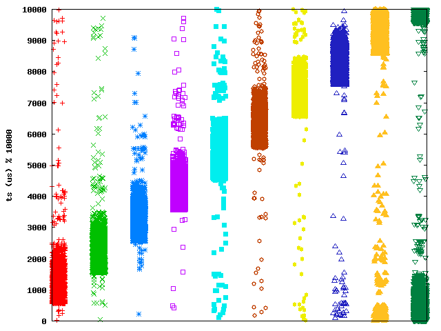
A straightforward implementation of one-millisecond slotting is to suspend and resume transmission from within Linux's timer interrupt handler in accordance with a station's assigned slot. However, the naïve approach faces two problems: clock skew and timer inaccuracy. Figure 5 illustrates both. In this experiment, a single station uses iperf to emulate a G.729 VoIP codec with a 10-ms inter-packet arrival rate. We manually assign the station a static TDMA slot; there is little to no background traffic on the same AP during the experiment
In the figure, the x axis plots time in seconds, and the y axis shows the start time of each transmission modulo 10,000 us (10 ms). The figure shows the effect of the timer interrupt firing faster than 1,000 times per second as well as iperf sending slightly slower than the configured rate of 100 packets per second. If the timer interrupt and iperf operated at their correct rate, we would expect to see a single horizontal band corresponding to the station's assigned slot. Instead, iperf schedules packets at a rate slower than the timer interrupt, and as a result iperf and the implemented TDMA slot drift with respect to each other. When iperf happens to send inside the slot, a short almost horizontal line appears starting at the bottom of the slot (the slight upward slope of this line is the clock skew). Once transmissions reach the top of the slot, packets are buffered until the start of the next slot, causing the downward sloping lines. The slope is caused by the timer interrupt firing too fast.
Different stations may exhibit different degrees of skew, possibly even varying across time. We address this issue by effectively slaving each station's clock to an AP. Specifically, we reset the timer every time a station hears the periodic beacon frame from the AP that was assigned during the slot allocation process. On the Soekris net4801 in our testbed, Linux uses the programmable interval timer (PIT) as its time interrupt source. Therefore, we modify the driver to reset the PIT every time it hears a beacon, which we have measured to be roughly once every 102-103 ms for the APs in our network.
Manipulating the PIT timer in this way may conceivably cause unintended timing artifacts in the station's operation. Therefore, we have developed an alternative implementation that uses Linux's high-resolution timers to schedule the VoIP slots and have observed a similar degree of synchronization. However, the results in this paper are based on manipulating the PIT timer.
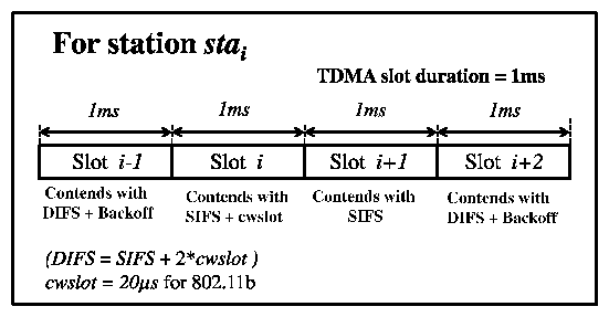
In standard DCF, stations contend using an inter-frame spacing of SIFS + (2·cwslot) followed by a random backoff. (By cwslot we denote an 802.11 contention-window slot-20 us in 802.11b-not Softspeak's 1-ms TDMA slot.) We use the two 20-us cwslot intervals starting at SIFS and (SIFS+cwslot), respectively, to (a) prioritize the VoIP traffic over non-VoIP traffic and (b) prioritize among different VoIP stations to avoid collisions. Accordingly, we let each station contend as follows: Figure 6 considers a station stai which is assigned TDMA slot i. During the station's assigned TDMA slot it contends with (SIFS+cwslot) (and no backoff). In slot i+1, it contends with SIFS (and no backoff). In any other slot it contends as specified by DCF (SIFS + (2·cwslot) + backoff).
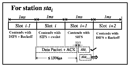
Now let us consider the scenario as illustrated in Figure 7, in which a station stai in TDMA slot i is delayed into the next TDMA slot (i+1) by an ongoing transmission and assume for the moment that stai's packet was ready at the start of the slot i. After the transmission has ended, stations stai and stai+1 contend for the channel. However, due to the assigned contention parameters, stai is guaranteed to win over station stai+1. Furthermore, after stai has finished transmitting and received its ACK (after 430 us for a large-payload G.711 codec), there is still at least (2 ms - 1376 us - 430 us = 194 us) for stai+1 to commence its transmission and therefore not contend in TDMA slot (i+2). It can be shown that in the absence of retransmissions, as long as (a) the duration of a VoIP frame is less than one TDMA slot and (b) the duration of a bulk frame is less than two TDMA slots, station i will never contend in slot (i+2). Even if due to, e.g., 802.11 retransmissions or imperfect control of timing by Softspeak, a station ends up contending in a TDMA slot other than i or (i+1), it will do so using conventional DCF contention parameters and do no worse than without our improvements.
Figure 8 plots the transmission start times of ten VoIP stations, each assigned a separate TDMA slot, when competing against background traffic. In particular, a bulk UDP sender generates background traffic in the downlink direction to a separate wireless station. Using dynamic IFS, the slotting is clearly defined: while the bands are longer than 1 ms due to delays caused by ongoing background traffic transmissions (as explained above), the majority of transmissions do not commence more than one slot away.
The first slot (assigned to the VoIP station plotted in the first column of Figure 8) commences roughly 500 us after the beacon time. This offset is caused by inevitable delays between the time that the beacon is generated by the AP and when it is received and processed by a station, and also between the time the station driver generates a packet for a particular slot and the time that it is transmitted. In particular, 400 us of this time is accounted for by beacon transmission time, the remainder consisting of processing delays in the station. While some of these processing delays may vary across different stations, as subsequent figures show, the delay is consistent enough across multiple stations with the same hardware configuration that a station's synchronization can be tuned for that hardware.
When a new Softspeak VoIP session starts up (or when the station roams to a different AP) it registers with the aggregator node, which we implement on a separate Linux machine. When the aggregator receives a downlink packet addressed to a registered VoIP client, it buffers the packet and combines it with all other buffered packets into a single encapsulated packet that it sends out at fixed intervals (e.g., 10 ms for G.729). The aggregator node uses the IP header information from the most recently heard uplink packet (say from station S1) to construct a new frame. Addressing the packet to S1 increases the likelihood that the packet will be acknowledged by a currently active VoIP client. We define an aggregation header that stores the set of destinations and original IP packet lengths for each station. The aggregation header is prepended to the UDP header and packet payload for S1, and then the respective IP and UDP headers and payloads for the remaining buffered VoIP packets are appended.
In contrast to previous proposals [23], we address the aggregated frame to only one of the VoIP stations; we configure the WiFi interface of each of the VoIP stations to be in promiscuous mode to allow them to receive the aggregated packets regardless of the destination. The client passes aggregated packets to the Softspeak module that de-encapsulates the packet, extracts the portion meant for the current station, and passes it up the networking stack. Because the aggregated packet is addressed to only one station, there will be at most one MAC-layer acknowledgment. Wang et al., on the other hand, propose the use of multicast in order to eliminate the MAC ACK frame. We preserve the ACK frame for two pragmatic reasons. First, in our experience, while obviously unable to eliminate all loss, the single ACK frame is a cost-effective mechanism to protect the aggregated packet against many collisions. Secondly, and perhaps more importantly, commodity access points typically transmit multicast frames only at a multiple of the beacon interval to inter-operate with clients in power-save mode, introducing intolerable delay.
We employ ten commodity PCs connected over wired gigabit Ethernet as endpoints for the (emulated) VoIP traffic generated by the Soekris boxes. Essentially, each PC-Soekris pair serves as a distinct bi-directional VoIP call. One additional PC-Soekris pair conducts a bulk transfer (TCP or UDP) to measure the residual capacity of the wireless channel in the presence of the VoIP traffic. The TCP receive-window size is configured to be large enough that our TCP transfers are never receive-window limited. Unless otherwise noted, bulk transfer is conducted through the Atheros card, while the Ralink interfaces send and receive VoIP traffic.
| Card | CWmin | CWmax | Retry limit |
| Ralink RT2560F | 8 | 256 | 8 |
| Atheros AR5212 | 32 | 32 | 11 |
| Avaya AP-8 | 16 | 16 | 11 |
Table 1 reports the default contention parameters for the various devices in our testbed as measured by the Jigsaw wireless monitoring infrastructure [5]. We note that neither the Atheros card nor the Avaya AP appears to double its contention window size on retries, in contrast with the default behavior specified by 802.11.
 (a) Capacity
|
 (b) Downlink MOS
|
 (c) Uplink MOS
|
 (a) Capacity
|
 (b) Downlink MOS.
|
 (c) Uplink MOS
|
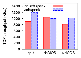
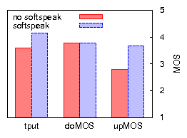
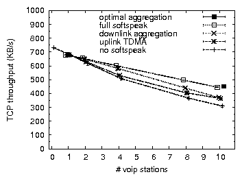
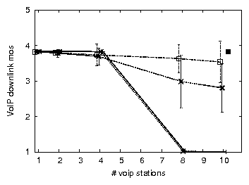
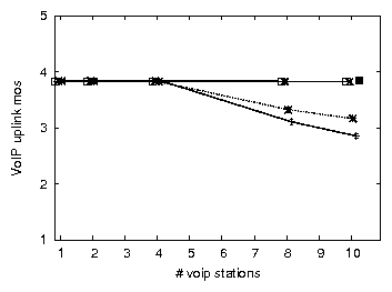
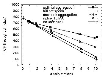
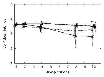
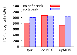
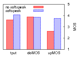
Figures 9 and 10 compare bulk throughput and VoIP call quality across all combinations of applying uplink TDMA and/or downlink aggregation in 802.11b, for TCP uplink and downlink. The results for UDP bulk uplink (not shown) are similar to those of TCP uplink. We discuss the case of UDP bulk downlink in Section 4.3. The most important conclusions are that (a) applying a combination of uplink TDMA and downlink aggregation improves residual bulk throughput, in some cases drastically, (b) with one exception, call quality is preserved or greatly improved, (c) applying only one of uplink TDMA or downlink aggregation does not achieve these results across all three cases of bulk traffic load.
We summarize the benefits of Softspeak (combined uplink TDMA and downlink aggregation) over 802.11, for the case of ten VoIP sessions, as follows:
While these results show that Softspeak improves the efficiency of 802.11b networks in the presence of VoIP in terms of residual TCP capacity (while mostly preserving VoIP call quality), an important question is whether further improvements to our implementation could be made. For example, it might be the case that our implementation of uplink TDMA lacks sufficient control of VoIP packet scheduling, causing collisions. An optimal implementation (e.g., one that is implemented in the 802.11 hardware or firmware) might do a better job at controlling the emission of frames according to the TDMA schedule.
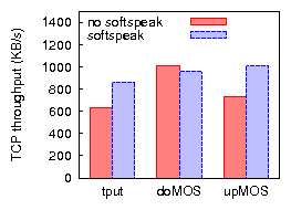
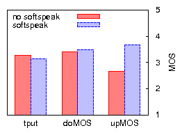
To investigate to what extent further improvements may be made to our implementation (but while remaining faithful to Softspeak), we compare our results with those based on an emulation of an optimal implementation. We emulate downlink aggregation by replacing the individual VoIP senders that generate downlink VoIP traffic by a single sender that generates packets of the size produced by the downlink aggregator, eliminating any jitter and loss potentially caused by the downlink aggregator. Furthermore, downlink packets are sent to, and their loss rate measured at, a single VoIP station, eliminating any losses due to imperfect overhearing. We emulate uplink TDMA by replacing the VoIP stations by a single VoIP station that sends packets on behalf of all VoIP stations, in other words, it sends packets at ten times the codec rate. The single VoIP station naturally serializes the transmission of uplink VoIP packets, thereby eliminating any collision among VoIP stations. To minimize the probability of colliding with other traffic, it uses SIFS without backoff. In Figures 9 and 10 the results of the emulation are plotted as an `optimal' point for ten VoIP clients. In terms of capacity and uplink MOS, Softspeak achieves close to what is optimally achievable. For downlink MOS, consistent with our earlier observation, Softspeak performs worse than optimal due to imperfect overhearing. However, note that in Figure 10(b) even optimal Softspeak's downlink MOS is worse than that of `no softspeak'. This may be expected, given that (optimal) Softspeak enables TCP traffic to considerably increase network resource usage. For example, we measure a 25% increase in RTT (as well as an increased RTT variance) due to a higher AP queue occupation, which in turn explains the higher loss rate of downlink VoIP traffic.
| Metric | No Spk | Spk | Spk+Prio |
| Downlink bulk tput (KB/s) | 375 | 605 | 561 |
| Downlink VoIP loss rate | 67% | 61% | < 0.1% |
| Uplink VoIP loss rate | 0.82% | < 0.1% | < 0.1% |
Implementing Softspeak in our simulator also allows us to isolate the source of our performance improvement. Figure 11 shows the simulated airtime plot corresponding to Figure 4, but with uplink TDMA and downlink aggregation enabled (and no prioritization). The figure indicates that we have achieved our objective of converting almost all time spent on downlink framing overhead and on collision into bulk data capacity. Consistent with the reduction in collision airtime we have also reduced the collision rate, thereby improving loss rate, jitter, and as a result, VoIP call quality and TCP throughput.
| Softspeak enabled | No measures | Fixed=11b | Fixed=11b, |
| optout | |||
| No | 3.7 +/- 0.095 | ||
| Yes | 2.8 +/- 1.0 | ||
| Yes, fixed Station 1 | 3.4 +/- 0.63 | 3.5 +/- 0.23 | |
| Yes, fixed Station 2 | 2.7 +/- 1.0 | 3.2 +/- 0.81 | 3.5 +/- 0.31 |
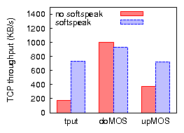
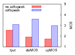
For 802.11g we observe that Softspeak as currently described makes significant improvements in capacity (24-32% for ten VoIP stations), while maintaining or lowering jitter and VoIP uplink loss to negligible levels. Recall that when 802.11g runs in protected mode, TCP downlink capacity suffers tremendously in the presence of VoIP. Using Softspeak we are able to triple (increase by 200%) the TCP downlink capacity for ten VoIP stations. However, Softspeak also introduces significant downlink VoIP loss, rising to 30% for some stations, where in some cases virtually none was experienced without enabling Softspeak. In the case of 802.11g protected mode this reduces MOS from 3.7 to 2.8 on average and substantially increases the variance of MOS (Table 3, no measures).
As noted in Section 4.2 for 802.11b, downlink aggregation is susceptible to frame corruption by any receiver that is not the link-layer recipient of the aggregated packet, and the higher rates of 802.11g only increase the likelihood of frame corruption. Our solution to this problem is three-fold. First, we observe that judiciously selecting a fixed station as the destination for aggregated packets may greatly alleviate loss: picking a station that consistently experiences frame corruption causes the AP to often retransmit aggregated frames thereby increasing each station's probability of receiving a correct copy. For a particular choice of station (Station 1 in Table 3), we observe that the average downlink loss rate consistently reduces to below 2%, resulting in an average MOS of 3.4. However, the MOS variance remains high. Second, the selected station can be made to associate with the AP at a lower rate, causing aggregated packets to be transmitted at the lower rate and further reducing frame corruption. To test this, we force Station 1 to associate in 802.11b mode (fixed=11b in Table 3) and obtain a MOS of 3.5 as well as reduced variance. Note that to avoid condemning one of the stations to low-rate communication, a dummy 802.11 receiver can be added to the downlink aggregator box (or placed separately) and made to associate at the lower rate.
Our third measure is to have any remaining bad receivers opt out of the downlink portion of Softspeak (not evaluated for Station 1). By de-registering with the aggregator, these clients receive separate VoIP frames as in the non-aggregated case (while continuing to measure loss rate from received aggregated packets to help decide whether and when to re-register). Note that these stations can still participate in uplink aggregation. To demonstrate that such a scheme can gracefully address this situation in practice, we evaluate all three measures when making a poor choice for the fixed station: Station 2 in Table 3, which gives a low MOS value of 2.7. After making the fixed station associate in 802.11b (improving average MOS to 3.2), we find that two stations consistently experience a high loss rate and MOS. Once these two stations opt out of downlink aggregation, we arrive at a MOS of 3.5 with low variance (fixed=11b,optout).
(a) TCP downlink. |
(b) TCP uplink. |
(a) TCP downlink. |
(b) TCP uplink. |
Of course, several of these measures have the potential of sacrificing much of the bulk traffic throughput gains that were obtained from downlink aggregation in the first place. We evaluate both TCP throughput and VoIP quality based on the above Station 2 and while applying all three measures. Downlink TCP throughput (Figure 12(a)) does not much suffer much from these countermeasures: Softspeak continues to more than triple TCP downlink throughput. However, the resulting uplink TCP throughput (781KB/s, Figure 12(b)) is 12% less than the throughput achievable by Softspeak without enabling these countermeasures (not shown). Nevertheless, even with the countermeasures enabled Softspeak is able to achieve a significant improvement on residual throughput (34%) on TCP uplink traffic. For both TCP downlink and uplink Softspeak mostly maintains or significantly improves VoIP quality. For completeness, Figure 13 presents the corresponding results when all clients use a 20-ms G.729 codec. As expected, Softspeak delivers less benefit in terms of throughput increase, yet remains critical for uplink VoIP call quality.
|
|
So far we have focused on Softspeak's impact on bulk traffic, without other traffic present. In reality, of course, one may expect a diverse traffic mix. We next evaluate how our results change in the presence of Web traffic, by running an equal number of VoIP clients and Web clients in combination with a bulk TCP stream, where each of the Web clients repeatedly downloads the front page of www.cnn.com (630 KB). Note that the size of our testbed limits us to five VoIP clients and five Web clients, and the magnitude of improvement is expected to be smaller than for a larger number of clients. In Figure 14, we plot Softspeak's improvements before (a and b) and after (c and d) adding Web traffic. Comparing the two scenarios we find that, independent of the presence of Web traffic, Softspeak (a) raises uplink MOS to an identical level, (b) roughly maintains downlink MOS, and (c) improves downlink TCP throughput to the same degree (roughly 35%). However, we also find that the gains made by Softspeak on TCP uplink throughput diminish in the presence of Web traffic. In summary, it appears that, with the exception of TCP uplink throughput, Softspeak's improvements on the efficiency of the network are maintained, even when Web traffic is present.
Softspeak relies on clients overhearing each other's VoIP communication to perform downlink aggregation. Therefore, if a WLAN uses a WiFi encryption protocol such as WPA2, downlink aggregation is no longer possible. Uplink TDMA, on the other hand, is not affected by encryption. Protocols encrypted above the MAC layer, such as Skype, can continue to take advantage of Softspeak's downlink aggregation, as long as they allow some way of being detected as VoIP.
Another consequence of downlink aggregation is that Softspeak places a station's interface in promiscuous mode, raising concerns of increased power usage. Stations engaging in VoIP traffic cannot currently benefit from 802.11 power saving mode (PSM) with or without Softspeak enabled, since PSM's duty cycling granularity is too coarse (a multiple of the beacon interval time). However, Softspeak introduces a well-defined schedule, both for uplink (TDMA) and downlink traffic (the aggregator's schedule), even in the face of jitter caused by VoIP applications or the wide-area network. Future rapid-duty cycling hardware may be able to exploit Softspeak to provide more fine-grained power savings.
VoIP silence suppression may go some way towards mitigating the impact of VoIP, decreasing the need for Softspeak. However, it appears that silence suppression is not universally implemented or supported by all codecs. For example, while monitoring a G.711 call between a Linksys VoIP phone and a softphone (Twinkle), we observe no change to inter-packet time in traffic sent by either side, even when the sender is muted. The same applies when we monitor a SkypeOut call. On the other hand, we have observed that Skype-to-Skype calls do employ silence suppression by lowering the sending rate, rather than eliminating traffic completely.
The poor performance of VoIP in WiFi networks is not protocol specific, but is symptomatic of a general issue with any CSMA (carrier-sense, multiple-access) network: channel access and arbitration becomes increasingly inefficient as load (in terms of number of attempted channel accesses) increases. TDMA can be far more efficient under heavy load. Indeed, 802.11 includes both a point coordination function (PCF) mode and a hybrid coordination function (HCF) mode, in which the AP explicitly arbitrates channel access. Unfortunately, very few deployed 802.11 networks employ these modes.
If one considers modifying the hardware, a variety of options exist. For example, researchers have proposed modifying 802.11 PCF [3,11] as well as alternative ways of implementing 802.11e-like functionality [22]. Of course, non-backwards compatible modifications do not address the issue facing today's networks. Accordingly, researchers have proposed a variety of explicit time-slotting mechanisms, both within the context of infrastructure-based networks [10,15,16,18,21] and multi-hop mesh networks [13,17].
MadMAC [18], ARGOS [13], and the Overlay MAC Layer (OML) [17] each propose to enable time-slotting on the order of 20 ms. Snow et al. [21] present a similar TDMA-based approach to power savings where each slot is of the order of 100 ms and requires changes at the access points themselves. These scheduling granularities are too coarse to effectively support most VoIP codecs. While software TDMA (STDMA) [10] proposes to do TDMA for all traffic, they focus particularly on the performance of VoIP. Their approach is a substantial and backward-incompatible modification to 802.11 that requires accurate clock synchronization. More significantly, each of the above schemes require the entire network to support the new TDMA architecture with no support for unmodified clients.
Over and above TDMA mechanisms, the SoftMAC [15] and MultiMAC [8] projects also suggest modifications to 802.11 MAC behavior, including changing the ACK timing and modifying back-off parameters. The authors do not provide many details about their implementations, however, nor do they evaluate their scheme with deadline-driven VoIP traffic.
Focusing explicitly on improving the performance of VoIP traffic in mixed-use networks, various proposals have suggesting prioritizing VoIP traffic [4,25], notably a commercial product, Spectralink Voice Priority (SVP) [2]. SVP prioritizes downlink VoIP packets in the AP transmit queue and does not back-off when attempting VoIP transmissions. While we leverage similar optimizations, SVP does not do scheduling, thereby increasing collision rate due to the lack of back-off.
Finally, several studies [12,19] have shown using simulations that prioritizing traffic, using modified contention parameters, can lead to fairness and better resource allocation in both uplink and downlink directions. In contrast to our work, these proposals aim only to balance uplink and downlink traffic flows and do not evaluate TCP traffic in combination with VoIP traffic.
We present Softspeak, a set of backward-compatible changes to WiFi that address contention and framing overhead. We show that our dynamic IFS contention scheme, combined with downlink aggregation, dramatically reduces the impact of VoIP on network capacity yet improves call quality. Our project page (including audio samples) is at https://sysnet.ucsd.edu/wireless/softspeak/.