Maelstrom: Transparent Error Correction for Lambda Networks
Mahesh Balakrishnan, Tudor Marian, Ken Birman, Hakim Weatherspoon, Einar Vollset
{mahesh, tudorm, ken, hweather, einar}@cs.cornell.edu
Cornell University, Ithaca, NY-14853
Abstract
The global network of datacenters is emerging as an important distributed systems paradigm - commodity clusters running high-performance applications, connected by high-speed `lambda' networks across hundreds of milliseconds of network latency. Packet loss on long-haul networks can cripple application performance - a loss rate of 0.1% is sufficient to reduce TCP/IP throughput by an order of magnitude on a 1 Gbps link with 50ms latency. Maelstrom is an edge appliance that masks packet loss transparently and quickly from inter-cluster protocols, aggregating traffic for high-speed encoding and using a new Forward Error Correction scheme to handle bursty loss.
1 Introduction
The emergence of commodity clusters and datacenters has enabled a new class of globally distributed high-performance applications that coordinate over vast geographical distances. For example, a financial firm's New York City datacenter may receive real-time updates from a stock exchange in Switzerland, conduct financial transactions with banks in Asia, cache data in London for locality and mirror it to Kansas for disaster-tolerance.
To interconnect these bandwidth-hungry datacenters across the globe, organizations are increasingly deploying private `lambda' networks [39,35]. Raw bandwidth is ubiquitous and cheaply available in the form of existing `dark fiber'; however, running and maintaining high-quality loss-free networks over this fiber is difficult and expensive. Though high-capacity optical links are almost never congested, they drop packets for numerous reasons - dirty/degraded fiber [14], misconfigured/malfunctioning hardware[21,20] and switching contention [27], for example - and in different patterns, ranging from singleton drops to extended bursts [26,16].
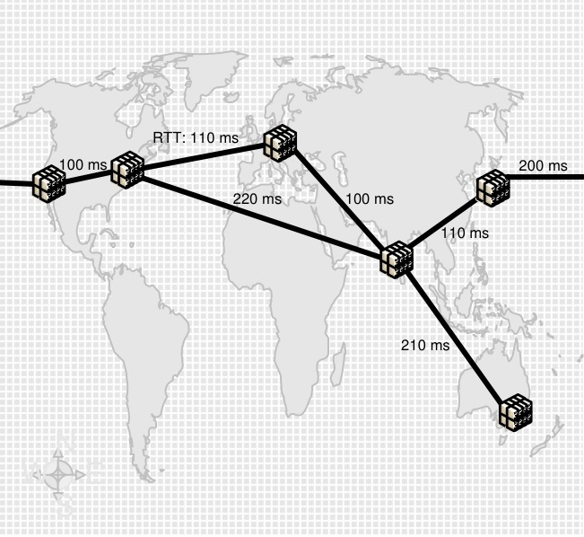 Figure 1: Example Lambda Network
Non-congestion loss has been observed on long-haul networks as well-maintained as Abilene/Internet2 and National LambdaRail [21,20,16,15] - as has its crippling effect on commodity protocols, motivating research into loss-resistant data transfer protocols [25,17,13,43,38]. Conservative flow control mechanisms designed to deal with the systematic congestion of the commodity Internet react too sharply to ephemeral loss on over-provisioned links - a single packet loss in ten thousand is enough to reduce TCP/IP throughput to a third over a 50 ms gigabit link, and one in a thousand drops it by an order of magnitude. Real-time applications are impacted by the reliance of reliability mechanisms on acknowledgments and retransmissions, limiting the latency of packet recovery to at least the Round Trip Time (RTT) of the link; if delivery is sequenced, each lost packet acts as a virtual `road-block' in the FIFO channel until it is recovered.
Figure 1: Example Lambda Network
Non-congestion loss has been observed on long-haul networks as well-maintained as Abilene/Internet2 and National LambdaRail [21,20,16,15] - as has its crippling effect on commodity protocols, motivating research into loss-resistant data transfer protocols [25,17,13,43,38]. Conservative flow control mechanisms designed to deal with the systematic congestion of the commodity Internet react too sharply to ephemeral loss on over-provisioned links - a single packet loss in ten thousand is enough to reduce TCP/IP throughput to a third over a 50 ms gigabit link, and one in a thousand drops it by an order of magnitude. Real-time applications are impacted by the reliance of reliability mechanisms on acknowledgments and retransmissions, limiting the latency of packet recovery to at least the Round Trip Time (RTT) of the link; if delivery is sequenced, each lost packet acts as a virtual `road-block' in the FIFO channel until it is recovered.
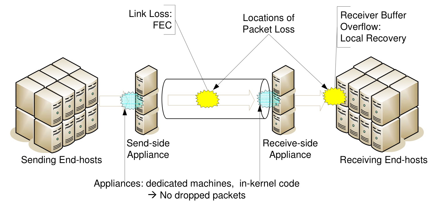
Figure 2: Maelstrom Communication Path
Deploying new loss-resistant protocols is not an alternative in corporate datacenters, where standardization is the key to low and predictable maintenance costs; neither is eliminating loss events on a network that could span thousands of miles. Accordingly, there is a need to mask loss on the link, rapidly and transparently. Rapidly, because recovery delays for lost packets translate into dramatic reductions in application-level throughput; and transparently, because applications and OS networking stacks in commodity datacenters cannot be rewritten from scratch.
Forward Error Correction (FEC) is a promising solution for reliability over long-haul links [36] - packet recovery latency is independent of the RTT of the link. While FEC codes have been used for decades within link-level hardware solutions, faster commodity processors have enabled packet-level FEC at end-hosts [37,18]. End-to-end FEC is very attractive for inter-datacenter communication: it's inexpensive, easy to deploy and customize, and does not require specialized equipment in the network linking the datacenters. However, end-host FEC has two major issues - First, it's not transparent, requiring modification of the end-host application/OS. Second, it's not necessarily rapid; FEC works best over high, stable traffic rates and performs poorly if the data rate in the channel is low and sporadic [6], as in a single end-to-end channel.
In this paper, we present the Maelstrom Error Correction appliance - a rack of proxies residing between a datacenter and its WAN link (see Figure 2). Maelstrom encodes FEC packets over traffic flowing through it and routes them to a corresponding appliance at the destination datacenter, which decodes them and recovers lost data. Maelstrom is completely transparent - it does not require modification of end-host software and is agnostic to the network connecting the datacenter. Also, it eliminates the dependence of FEC recovery latency on the data rate in any single node-to-node channel by encoding over the aggregated traffic leaving the datacenter. Finally, Maelstrom uses a new encoding scheme called layered interleaving, designed especially for time-sensitive packet recovery in the presence of bursty loss.
The contributions of this paper are as follows:
- We explore end-to-end FEC for long-distance communication between datacenters, and argue that the rate sensitivity of FEC codes and the opacity of their implementations present major obstacles to their usage.
- We propose Maelstrom, a gateway appliance that transparently aggregates traffic and encodes over the resulting high-rate stream.
- We describe layered interleaving, a new FEC scheme used by Maelstrom where for constant encoding overhead the latency of packet recovery degrades gracefully as losses get burstier.
- We discuss implementation considerations. We built two versions of Maelstrom; one runs in user mode, while the other runs within the Linux kernel.
- We evaluate Maelstrom on Emulab [45] and show that it provides near lossless TCP/IP throughput and latency over lossy links, and recovers packets with latency independent of the RTT of the link and the rate in any single channel.
2 Model
Our focus is on pairs of geographically distant datacenters that coordinate with each other in real-time. This has long been a critical distributed computing paradigm in application domains such as finance and aerospace; however, similar requirements are arising across the board as globalized enterprises rely on networks for high-speed communication and collaboration.
Traffic Model: The most general case of inter-cluster communication is one where any node in one cluster can communicate with any node in the other cluster. We make no assumptions about the type of traffic flowing through the link; mission-critical applications could send dynamically generated real-time data such as stock quotes, financial transactions and battleground location updates, while enterprise applications could send VoIP streams, ssh sessions and synchronous file updates between offices.
Loss Model: Packet loss typically occurs at two points in an end-to-end communication path between two datacenters, as shown in Figure 2 - in the wide-area network connecting them and at the receiving end-hosts. Loss in the lambda link can occur for many reasons, as stated previously: transient congestion, dirty or degraded fiber, malfunctioning or misconfigured equipment, low receiver power and burst switching contention are some reasons [23,14,21,20,27]. Loss can also occur at receiving end-hosts within the destination datacenter; these are usually cheap commodity machines prone to temporary overloads that cause packets to be dropped by the kernel in bursts [6] - this loss mode occurs with UDP-based traffic but not with TCP/IP, which advertises receiver windows to prevent end-host buffer overflows.
What are typical loss rates on long-distance optical networks? One source of information is TeraGrid [5], an optical network interconnecting major supercomputing sites in the US. TeraGrid has a monitoring framework within which ten sites periodically send each other 1 Gbps streams of UDP packets and measure the resulting loss rate [3]. Each site measures the loss rate to every other site once an hour, resulting in a total of 90 loss rate measurements collected across the network every hour. Between Nov 1, 2007 and Jan 25, 2007, 24% of all such measurements were over 0.01% and a surprising 14% of them were over 0.1%. After eliminating a single site (Indiana University) that dropped incoming packets steadily at a rate of 0.44%, 14% of the remainder were over 0.01% and 3% were over 0.1%.
These numbers reflect the loss rate experienced for UDP traffic on an end-to-end path and may not generalize to TCP packets. Also, we do not know if packets were dropped within the optical network or at intermediate devices within either datacenter, though it's unlikely that they were dropped at the end-hosts; many of the measurements lost just one or two packets whereas kernel/NIC losses are known to be bursty [6]. Further, loss occurred on paths where levels of optical link utilization (determined by 20-second moving averages) were consistently lower than 20%, ruling out congestion as a possible cause, a conclusion supported by dialogue with the network administrators [44].
Other data-points are provided by the back-bone networks of Tier-1 ISPs. Global Crossing reports average loss rates between 0.01% and 0.03% on four of its six inter-regional long-haul links for the month of December 2007 [1]. Qwest reports loss rates of 0.01% and 0.02% in either direction on its trans-pacific link for the same month [2]. We expect privately managed lambdas to exhibit higher loss rates due to the inherent trade-off between fiber/equipment quality and cost [10], as well as the difficulty of performing routine maintenance on long-distance links. Consequently, we model end-to-end paths as dropping packets at rates of 0.01% to 1%, to capture a wide range of deployed networks.
3 Existing Reliability Options
TCP/IP is the default reliable communication option for contemporary networked applications, with deep, exclusive embeddings in commodity operating systems and networking APIs. Consequently, most applications requiring reliable communication over any form of network use TCP/IP.
3.1 The problem with commodity TCP/IP
ACK/Retransmit + Sequencing: Conventional TCP/IP uses positive acknowledgments and retransmissions to ensure reliability - the sender buffers packets until their receipt is acknowledged by the receiver, and resends if an acknowledgment is not received within some time period. Hence, a lost packet is received in the form of a retransmission that arrives no earlier than 1.5 RTTs after the original send event. The sender has to buffer each packet until it's acknowledged, which takes 1 RTT in lossless operation, and it has to perform additional work to retransmit the packet if it does not receive the acknowledgment. Also, any packets that arrive with higher sequence numbers than that of a lost packet must be queued while the receiver waits for the lost packet to arrive.
Consider a high-throughput financial banking application running in a datacenter in New York City, sending updates to a sister site in Switzerland. The RTT value between these two centers is typically 100 milliseconds; i.e., in the case of a lost packet, all packets received within the 150 milliseconds between the original packet send and the receipt of its retransmission have to be buffered at the receiver.
Notice that for this commonplace scenario, the loss of a single packet stops all traffic in the channel to the application for a seventh of a second; a sequence of such blocks can have devastating effect on a high-throughput system where every spare cycle counts. Further, in applications with many fine-grained components, a lost packet can potentially trigger a butterfly effect of missed deadlines along a distributed workflow. During high-activity periods - market crashes at stock exchanges, Christmas sales at online stores, winter storms at air-traffic control centers - overloaded networks and end-hosts can exhibit continuous packet loss, with each lost packet driving the system further and further out of sync with respect to its real-world deadlines.
Sensitive Flow Control: TCP/IP is unable to distinguish between ephemeral loss modes - due to transient congestion, switching errors, or dirty fiber - and persistent congestion. The loss of one packet out of ten thousand is sufficient to reduce TCP/IP throughput to a third of its lossless maximum; if one packet is lost out of a thousand, throughput collapses to a thirtieth of the maximum.
3.2 The Case For (and Against) FEC
FEC encoders are typically parameterized with an (r,c) tuple - for each outgoing sequence of r data packets, a total of r+c data and error correction packets are sent over the channel 1. Significantly, redundancy information cannot be generated and sent until all r data packets are available for sending. Consequently, the latency of packet recovery is determined by the rate at which the sender transmits data. Generating error correction packets from less than r data packets at the sender is not a viable option - even though the data rate in this channel is low, the receiver and/or network could be operating at near full capacity with data from other senders.
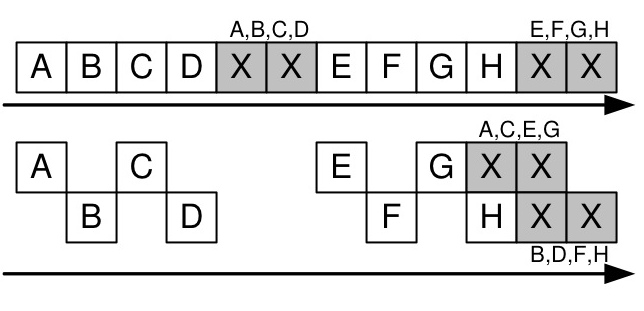
Figure 3: Interleaving with index 2: separate encoding for odd and even packets
FEC is also very susceptible to bursty losses [34]. Interleaving [32] is a standard encoding technique used to combat bursty loss, where error correction packets are generated from alternate disjoint sub-streams of data rather than from consecutive packets. For example, with an interleave index of 3, the encoder would create correction packets separately from three disjoint sub-streams: the first containing data packets numbered (0, 3, 6... (r-1)*3), the second with data packets numbered (1, 4, 7... (r-1)*3+1), and the third with data packets numbered (2, 5, 8, ... (r-1)*3+2). Interleaving adds burst tolerance to FEC but exacerbates its sensitivity to sending rate - with an interleave index of i and an encoding rate of (r,c), the sender would have to wait for i*(r-1)+1 packets before sending any redundancy information.
These two obstacles to using FEC in time-sensitive settings - rate sensitivity and burst susceptibility - are interlinked through the tuning knobs: an interleave of i and a rate of (r,c) provides tolerance to a burst of up to c*i consecutive packets. Consequently, the burst tolerance of an FEC code can be changed by modulating either the c or the i parameters. Increasing c enhances burst tolerance at the cost of network and encoding overhead, potentially worsening the packet loss experienced and reducing throughput. In contrast, increasing i trades off recovery latency for better burst tolerance without adding overhead - as mentioned, for higher values of i, the encoder has to wait for more data packets to be transmitted before it can send error correction packets.
Importantly, once the FEC encoding is parameterized with a rate and an interleave to tolerate a certain burst length B (for example, r=5, c=2 and i=10 to tolerate a burst of length 2*10=20), all losses occurring in bursts of size less than or equal to B are recovered with the same latency - and this latency depends on the i parameter. Ideally, we'd like to parameterize the encoding to tolerate a maximum burst length and then have recovery latency depend on the actual burstiness of the loss. At the same time, we would like the encoding to have a constant rate for network provisioning and stability. Accordingly, an FEC scheme is required where latency of recovery degrades gracefully as losses get burstier, even as the encoding overhead stays constant.
4 Maelstrom Design and Implementation
We describe the Maelstrom appliance as a single machine - later, we will show how more machines can be added to the appliance to balance encoding load and scale to multiple gigabits per second of traffic.
4.1 Basic Mechanism
The basic operation of Maelstrom is shown in Figure 4 - at the send-side datacenter, it intercepts outgoing data packets and routes them to the destination datacenter, generating and injecting FEC repair packets into the stream in their wake. A repair packet consists of a `recipe' list of data packet identifiers and FEC information generated from these packets; in the example in Figure 4, this information is a simple XOR. The size of the XOR is equal to the MTU of the datacenter network, and to avoid fragmentation of repair packets we require that the MTU of the long-haul network be set to a slightly larger value. This requirement is usually satisfied in practical deployments, since gigabit links very often use `Jumbo' frames of up to 9000 bytes [19] while LAN networks have standard MTUs of 1500 bytes.
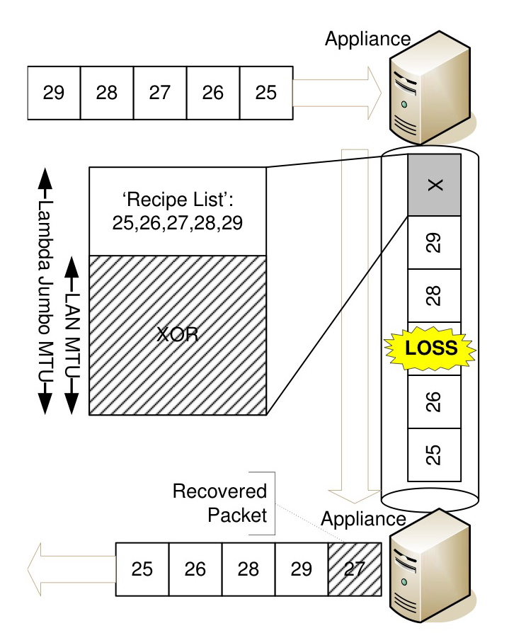
Figure 4: Basic Maelstrom mechanism: repair packets are injected into stream transparently
At the receiving datacenter, the appliance examines incoming repair packets and uses them to recover missing data packets. On recovery, the data packet is injected transparently into the stream to the receiving end-host. Recovered data packets will typically arrive out-of-order, but this behavior is expected by communication stacks designed for the commodity Internet.
4.2 Flow Control
While relaying TCP/IP data, Maelstrom has two flow control modes: end-to-end and split. With end-to-end flow control, the appliance routes packets through without modification, allowing flow-control between the end-hosts. In split mode, the appliance acts as a TCP/IP endpoint, terminating connections and sending back ACKs immediately before relaying data on appliance-to-appliance flows; this is particularly useful for applications with short-lived flows that need to ramp up throughput quickly and avoid the slow-start effects of TCP/IP on a long link. The performance advantages of splitting long-distance connections into multiple hops are well known [7] and orthogonal to this work; we are primarily interested in isolating the impact of rapid and transparent recovery of lost packets by Maelstrom on TCP/IP, rather than the buffering and slow-start avoidance benefits of generic performance-enhancing proxies. In the remainder of the paper, we describe Maelstrom with end-to-end flow control.
Is Maelstrom TCP-Friendly? While Maelstrom respects end-to-end flow control connections (or splits them and implements its own proxy-to-proxy flow control as described above), it is not designed for routinely congested networks; the addition of FEC under TCP/IP flow control allows it to steal bandwidth from other competing flows running without FEC in the link, though maintaining fairness versus similarly FEC-enhanced flows [30]. However, friendliness with conventional TCP/IP flows is not a primary protocol design goal on over-provisioned multi-gigabit links, which are often dedicated to specific high-value applications. We see evidence for this assertion in the routine use of parallel flows [38] and UDP `blast' protocols [43,17] both in commercial deployments and by researchers seeking to transfer large amounts of data over high-capacity academic networks.
4.3 Layered Interleaving
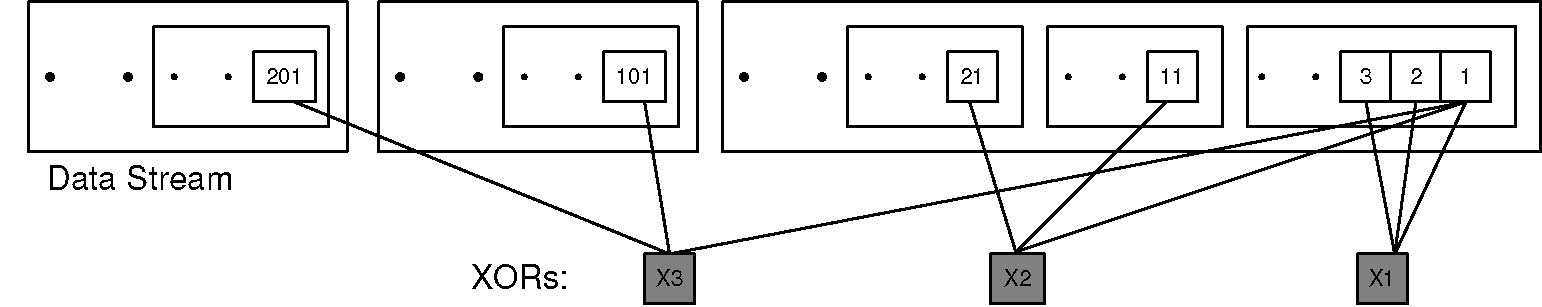
Figure 5: Layered Interleaving: (r=3, c=3), I=(1,10,100)
In layered interleaving, an FEC protocol with rate (r,c) is produced by running c multiple instances of an (r,1) FEC protocol simultaneously with increasing interleave indices I = (i0, i1, i2 ... ic-1). For example, if r=8, c=3 and I=(i0=1,i1=10,i2=100), three instances of an (8,1) protocol are executed: the first instance with interleave i0=1, the second with interleave i1=10 and the third with interleave i2=100. An (r,1) FEC encoding is simply an XOR of the r data packets - hence, in layered interleaving each data packet is included in c XORs, each of which is generated at different interleaves from the original data stream. Choosing interleaves appropriately (as we shall describe shortly) ensures that the c XORs containing a data packet do not have any other data packet in common. The resulting protocol effectively has a rate of (r,c), with each XOR generated from r data packets and each data packet included in c XORs. Figure 5 illustrates layered interleaving for a (r=3,c=3) encoding with I=(1,10,100).
As mentioned previously, standard FEC schemes can be made resistant to a certain loss burst length at the cost of increased recovery latency for all lost packets, including smaller bursts and singleton drops. In contrast, layered interleaving provides graceful degradation in the face of bursty loss for constant encoding overhead - singleton random losses are recovered as quickly as possible, by XORs generated with an interleave of 1, and each successive layer of XORs generated at a higher interleave catches larger bursts missed by the previous layer.
The implementation of this algorithm is simple and shown in Figure 6 - at the send-side proxy, a set of repair bins is maintained for each layer, with i bins for a layer with interleave i. A repair bin consists of a partially constructed repair packet: an XOR and the `recipe' list of identifiers of data packets that compose the XOR. Each intercepted data packet is added to each layer - where adding to a layer simply means choosing a repair bin from the layer's set, incrementally updating the XOR with the new data packet, and adding the data packet's header to the recipe list. A counter is incremented as each data packet arrives at the appliance, and choosing the repair bin from the layer's set is done by taking the modulo of the counter with the number of bins in each layer: for a layer with interleave 10, the xth intercepted packet is added to the (x mod 10)th bin. When a repair bin fills up - its recipe list contains r data packets - it `fires': a repair packet is generated consisting of the XOR and the recipe list and is scheduled for sending, while the repair bin is re-initialized with an empty recipe list and blank XOR.
At the receive-side proxy, incoming repair packets are processed as follows: if all the data packets contained in the repair's recipe list have been received successfully, the repair packet is discarded. If the repair's recipe list contains a single missing data packet, recovery can occur immediately by combining the XOR in the repair with the other successfully received data packets. If the repair contains multiple missing data packets, it cannot be used immediately for recovery - it is instead stored in a table that maps missing data packets to repair packets. Whenever a data packet is subsequently received or recovered, this table is checked to see if any XORs now have singleton losses due to the presence of the new packet and can be used for recovering other missing packets.
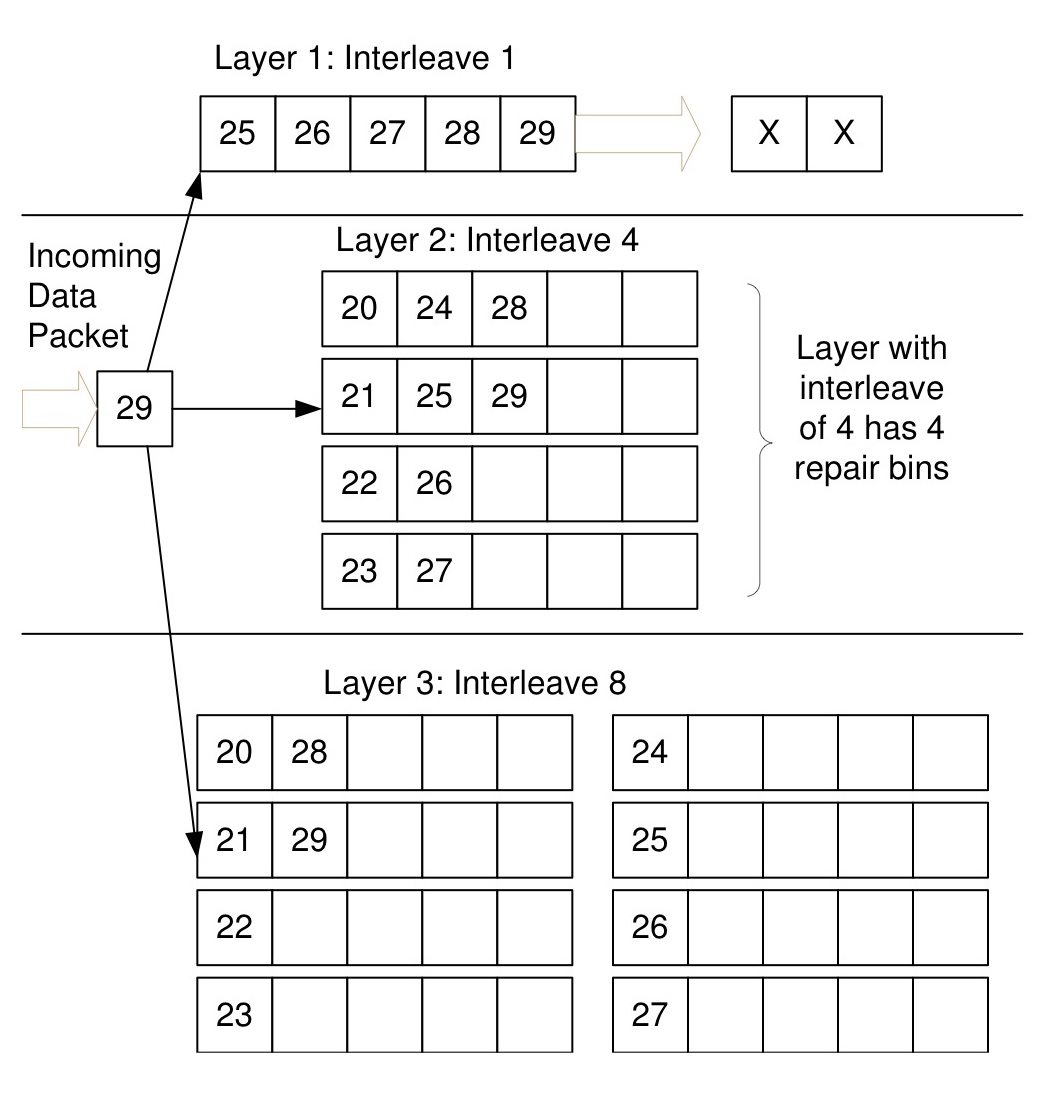
Figure 6: Layered Interleaving Implementation: (r=5, c=3), I=(1,4,8)
Importantly, XORs received from different layers interact to recover missing data packets, since an XOR received at a higher interleave can recover a packet that makes an earlier XOR at a lower interleave usable - hence, though layered interleaving is equivalent to c different (r,1) instances in terms of overhead and design, its recovery power is much higher and comes close to standard (r,c) algorithms.
4.3.1 Optimizations
Staggered Start for Rate-Limiting In the naive implementation of the layered interleaving algorithm, repair packets are transmitted as soon as repair bins fill and allow them to be constructed. Also, all the repair bins in a layer fill in quick succession; in Figure 6, the arrival of packets 36, 37, 38 and 39 will successively fill the four repair bins in layer 2. This behavior leads to a large number of repair packets being generated and sent within a short period of time, which results in undesirable overhead and traffic spikes; ideally, we would like to rate-limit transmissions of repair packets to one for every r data packets.

Figure 7: Staggered Start
This problem is fixed by `staggering' the starting sizes of the bins, analogous to the starting positions of runners in a sprint; the very first time bin number x in a layer of interleave i fires, it does so at size x mod r. For example, in Figure 6, the first repair bin in the second layer with interleave 4 would fire at size 1, the second would fire at size 2, and so on. Hence, for the first i data packets added to a layer with interleave i, exactly i/r fire immediately with just one packet in them; for the next i data packets added, exactly i/r fire immediately with two data packets in them, and so on until r*i data packets have been added to the layer and all bins have fired exactly once. Subsequently, all bins fire at size r; however, now that they have been staggered at the start, only i/r fire for any i data packets. The outlined scheme works when i is greater than or equal to r, as is usually the case. If i is smaller than r, the bin with index x fires at ((x mod r) * r/i) - hence, for r=4 and i=2, the initial firing sizes would be 2 for the first bin and 4 for the second bin. If r and i are not integral multiples of each other, the rate-limiting still works but is slightly less effective due to rounding errors.
Delaying XORs
In the naive implementation, repair packets are transmitted as soon as they are generated. This results in the repair packet leaving immediately after the last data packet that was added to it, which lowers burst tolerance - if the repair packet was generated at interleave i, the resulting protocol can tolerate a burst of i lost data packets excluding the repair, but the burst could swallow both the repair and the last data packet in it as they are not separated by the requisite interleave. The solution to this is simple - delay sending the repair packet generated by a repair bin until the next time a data packet is added to the now empty bin, which happens i packets later and introduces the required interleave between the repair packet and the last data packet included in it.
Notice that although transmitting the XOR immediately results in faster recovery, doing so also reduces the probability of a lost packet being recovered. This trade-off results in a minor control knob permitting us to balance speed against burst tolerance; our default configuration is to transmit the XOR immediately.
4.4 Back-of-the-Envelope Analysis
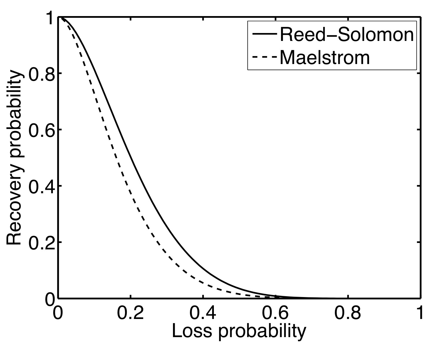
Figure 8: Comparison of Packet Recovery Probability: r=7, c=2
To start with, we note that no two repair packets generated at different interleaves i1 and i2 (such that i1 < i2) will have more than one data packet in common as long as the Least Common Multiple (LCM) of the interleaves is greater than r*i1; pairings of repair bins in two different layers with interleaves i1 and i2 occur every LCM(i1,i2) packets. Thus, a good rule of thumb is to select interleaves that are relatively prime to maximize their LCM, and also ensure that the larger interleave is greater than r.
Let us assume that packets are dropped with uniform, independent probability p. Given a lost data packet, what is the probability that we can recover it? We can recover a data packet if at least one of the c XORs containing it is received correctly and `usable', i.e, all the other data packets in it have also been received correctly, the probability of which is simply (1-p)r-1. The probability of a received XOR being unusable is the complement: (1 - (1-p)r-1).
Consequently, the probability x of a sent XOR being dropped or unusable is the sum of the probability that it was dropped and the probability that it was received and unusable: x = p + (1-p)(1-(1-p)r-1) = (1-(1-p)r).
Since it is easy to ensure that no two XORs share more than one data packet, the usability probabilities of different XORs are independent. The probability of all the c XORs being dropped or unusable is xc; hence, the probability of correctly receiving at least one usable XOR is 1-xc. Consequently, the probability of recovering the lost data packet is 1-xc, which expands to 1-(1-(1-p)r)c.
This closed-form formula only gives us a lower bound on the recovery probability, since the XOR usability formula does not factor in the probability of the other data packets in the XOR being dropped and recovered.
Now, we extend the analysis to bursty losses. If the lost data packet was part of a loss burst of size b, repair packets generated at interleaves less than b are dropped or useless with high probability, and we can discount them. The probability of recovering the data packet is then 1-xc¢, where c¢ is the number of XORs generated at interleaves greater than b. The formulae derived for XOR usability still hold, since packet losses with more than b intervening packets between them have independent probability; there is only correlation within the bursts, not between bursts.
How does this compare to traditional (r,c) codes such as Reed-Solomon [46]? In Reed-Solomon, c repair packets are generated and sent for every r data packets, and the correct delivery of any r of the r+c packets transmitted is sufficient to reconstruct the original r data packets. Hence, given a lost data packet, we can recover it if at least r packets are received correctly in the encoding set of r+c data and repair packets that the lost packet belongs to. Thus, the probability of recovering a lost packet is equivalent to the probability of losing c-1 or less packets from the total r+c packets. Since the number of other lost packets in the XOR is a random variable Y and has a binomial distribution with parameters (r+c-1) and p, the probability P(Y £ c-1) is the summation åz £ c-1P(Y = z). In Figure 8, we plot the recovery probability curves for Layered Interleaving and Reed-Solomon against uniformly random loss rate, for (r=7,c=2) - note that the curves are very close to each other, especially in the loss range of interest between 0% and 10%.
4.5 Local Recovery for Receiver Loss
In the absence of intelligent flow control mechanisms like TCP/IP's receiver-window advertisements, inexpensive datacenter end-hosts can be easily overwhelmed and drop packets during traffic spikes or CPU-intensive maintenance tasks like garbage collection. Reliable application-level protocols layered over UDP - for reliable multicast [6] or high speed data transfer [17], for example - would ordinarily go back to the sender to retrieve the lost packet, even though it was dropped at the receiver after covering the entire geographical distance.
The Maelstrom proxy acts as a local packet cache, storing incoming packets for a short period of time and providing hooks that allow protocols to first query the cache to locate missing packets before sending retransmission requests back to the sender. Future versions of Maelstrom could potentially use knowledge of protocol internals to transparently intervene; for example, by intercepting and satisfying retransmission requests sent by the receiver in a NAK-based protocol, or by resending packets when acknowledgments are not observed within a certain time period in an ACK-based protocol.
4.6 Implementation Details
We initially implemented and evaluated Maelstrom as a user-space proxy. Performance turned out to be limited by copying and context-switching overheads, and we subsequently reimplemented the system as a module that runs within the Linux 2.6.20 kernel. At an encoding rate of (8, 3), the experimental prototype of the kernel version reaches output speeds close to 1 gigabit per second of combined data and FEC traffic, limited only by the capacity of the outbound network card.
Of course, lambda networks are already reaching speeds of 40 gigabits, and higher speeds are a certainty down the road. To handle multi-gigabit loads, we envision Maelstrom as a small rack-style cluster of blade-servers, each acting as an individual proxy. Traffic would be distributed over such a rack by partitioning the address space of the remote datacenter and routing different segments of the space through distinct Maelstrom appliance pairs. In future work, we plan to experiment with such configurations, which would also permit us to explore fault-tolerance issues (if a Maelstrom blade fails, for example), and to support load-balancing schemes that might vary the IP address space partitioning dynamically to spread the encoding load over multiple machines. For this paper, however, we present the implementation and performance of a single-machine appliance.
The kernel implementation is a module for Linux 2.6.20 with hooks into the kernel packet filter [4]. Maelstrom proxies work in pairs, one on each side of the long haul link. Each proxy acts both as an ingress and egress router at the same time since they handle duplex traffic in the following manner:
- The egress router captures IP packets and creates redundant FEC packets. The original IP packets are routed through unaltered as they would have been originally; the redundant packets are then forwarded to the remote ingress router via a UDP channel.
- The ingress router captures and stores IP packets coming from the direction of the egress router. Upon receipt of a redundant packet, an IP packet is recovered if there is an opportunity to do so. Redundant packets that can be used at a later time are stored. If the redundant packet is useless it is immediately discarded. Upon recovery the IP packet is sent through a raw socket to its intended destination.
Using FEC requires that each data packet have a unique identifier that the receiver can use to keep track of received data packets and to identify missing data packets in a repair packet. If we had access to end-host stacks, we could have added a header to each packet with a unique sequence number [37]; however, we intercept traffic transparently and need to route it without modification or addition, for performance reasons. Consequently, we identify IP packets by a tuple consisting of the source and destination IP address, IP identification field, size of the IP header plus data, and a checksum over the IP data payload. The checksum over the payload is necessary since the IP identification field is only 16 bits long and a single pair of end-hosts communicating at high speeds will use the same identifier for different data packets within a fairly short interval unless the checksum is added to differentiate between them. Note that non-unique identifiers result in garbled recovery by Maelstrom, an event which will be caught by higher level checksums designed to deal with tranmission errors on commodity networks and hence does not have significant consequences unless it occurs frequently.
The kernel version of Maelstrom can generate up to a Gigabit per second of data and FEC traffic, with the input data rate depending on the encoding rate. In our experiments, we were able to saturate the outgoing card at rates as high as (8, 4), with CPU overload occurring at (8, 5) where each incoming data packet had to be XORed 5 times.
4.7 Buffering Requirements
At the receive-side proxy, incoming data packets are buffered so that they can be used in conjunction with XORs to recover missing data packets. Also, any received XOR that is missing more than one data packet is stored temporarily, in case all but one of the missing packets are received later or recovered through other XORs, allowing the recovery of the remaining missing packet from this XOR. In practice we stored data and XOR packets in double buffered red black trees - for 1500 byte packets and 1024 entries this occupies around 3 MB of memory.
At the send-side, the repair bins in the layered interleaving scheme store incrementally computed XORs and lists of data packet headers, without the data packet payloads, resulting in low storage overheads for each layer that rise linearly with the value of the interleave. The memory footprint for a long-running proxy was around 10 MB in our experiments.
4.8 Other Performance Enhancing Roles
Maelstrom appliances can optionally aggregate small sub-kilobyte packets from different flows into larger ones for better communication efficiency over the long-distance link. Additionally, in split flow control mode they can perform send-side buffering of in-flight data for multi-gigabyte flows that exceed the sending end-host's buffering capacity. Also, Maelstrom appliances can act as multicast forwarding nodes: appliances send multicast packets to each other across the long-distance link, and use IP Multicast [11] to spread them within their datacenters. Lastly, appliances can take on other existing roles in the datacenter, acting as security and VPN gateways and as conventional performance enhancing proxies (PEPs) [7].
5 Evaluation
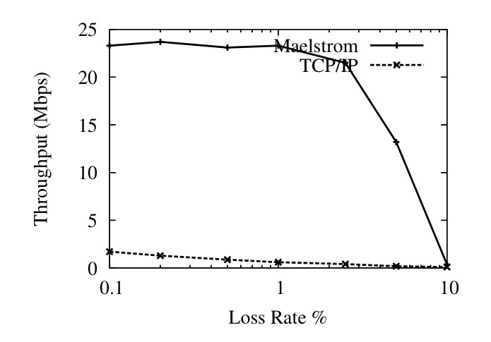
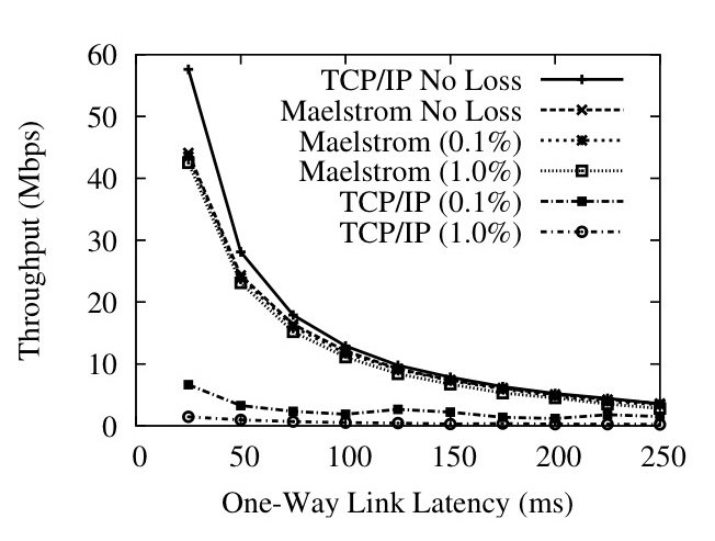
Figure 9: User-Space Throughput against (a) Loss Rate and (b) One-Way Latency
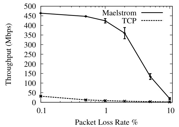
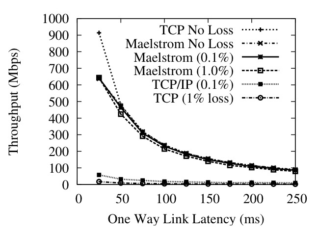
Figure 10: Kernel Throughput against (a) Loss Rate and (b) One-Way Latency
We evaluated Maelstrom on the Emulab testbed at Utah [45]. For all the experiments, we used a `dumbbell' topology of two clusters of nodes connected via routing nodes with a high-latency link in between them, designed to emulate the setup in Figure 2, and ran the proxy code on the routers. Figure 10 shows the performance of the kernel version at Gigabit speeds; the remainder of the graphs show the performance of the user-space version at slower speeds. To emulate the MTU difference between the long-haul link and the datacenter network (see Section 4.1) we set an MTU of 1200 bytes on the network connecting the end-hosts to the proxy and an MTU of 1500 bytes on the long-haul link between proxies; the only exception is Figure 10, where we maintained equal MTUs of 1500 bytes on both links.
5.1 Throughput Metrics
Figures 9 and 10 show that commodity TCP/IP throughput collapses in the presence of non-congestion loss, and that Maelstrom successfully masks loss and prevents this collapse from occurring. Figure 9 shows the performance of the user-space version on a 100 Mbps link and Figure 10 shows the kernel version on a 1 Gbps link. The experiment in each case involves running iperf [41] flows from one node to another across the long-distance link with and without intermediary Maelstrom proxies and measuring obtained throughput while varying loss rate (left graph on each figure) and one-way link latency (right graph). The error bars on the graphs to the left are standard errors of the throughput over ten runs; between each run, we flush TCP/IP's cache of tuning parameters to allow for repeatable results. The clients in the experiment are running TCP/IP Reno on a Linux 2.6.20 that performs autotuning. The Maelstrom parameters used are r=8,c=3, I=(1,20,40).
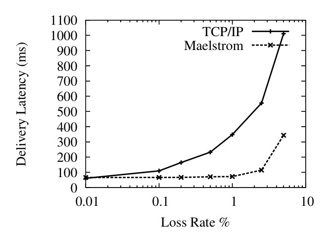
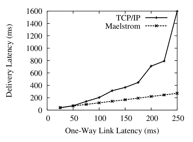
Figure 11: Per-Packet One-Way Delivery Latency against Loss Rate (Left) and Link Latency (Right)
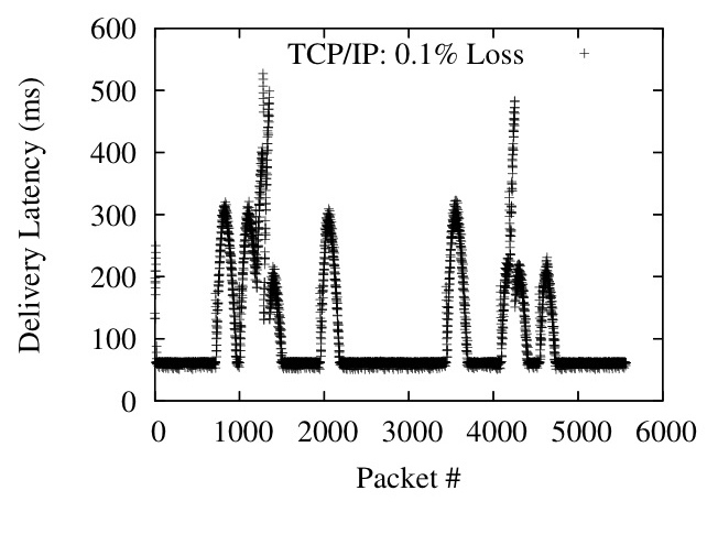
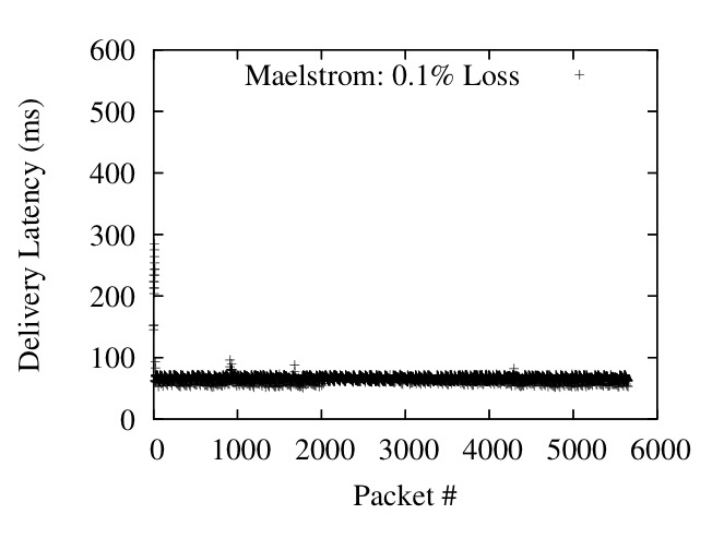
Figure 12: Packet delivery latencies
The user-space version involved running a single 10 second iperf flow from one node to another with and without Maelstrom running on the routers and measuring throughput while varying the random loss rate on the link and the one-way latency. To test the kernel version at gigabit speeds, we ran eight parallel iperf flows from one node to another for 120 seconds. The curves obtained from the two versions are almost identical; we present both to show that the kernel version successfully scales up the performance of the user-space version to hundreds of megabits of traffic per second.
In Figures 9 (Left) and 10 (Left), we show how TCP/IP performance degrades on a 50ms link as the loss rate is increased from 0.01% to 10%. Maelstrom masks loss up to 2% without significant throughput degradation, with the kernel version achieving two orders of magnitude higher throughput that conventional TCP/IP at 1% loss.
The graphs on the right side of Figures 9 and 10 show TCP/IP throughput declining on a link of increasing length when subjected to uniform loss rates of 0.1% and 1%. The top line in the graphs is the performance of TCP/IP without loss and provides an upper bound for performance on the link. In both user-space and kernel versions, Maelstrom masks packet loss and tracks the lossless line closely, lagging only when the link latency is low and TCP/IP's throughput is very high.
To allow TCP/IP to attain very high speeds on the gigabit link, we had to set the MTU of the entire path to be the maximum 1500 bytes, which meant that the long-haul link had the same MTU as the inter-cluster link. This resulted in the fragmentation of repair packets sent over UDP on the long-haul link into two IP packet fragments. Since the loss of a single fragment resulted in the loss of the repair, we observed a higher loss rate for repairs than for data packets. Consequently, we expect performance to be better on a network where the MTU of the long-haul link is truly larger than the MTU within each cluster.
5.2 Latency Metrics
To measure the latency effects of TCP/IP and Maelstrom, we ran a 0.1 Mbps stream between two nodes over a 100 Mbps link with 50 ms one-way latency, and simultaneously ran a 10 Mbps flow alongside on the same link to simulate a real-time stream combined with other inter-cluster traffic. Figure 11 (Left) shows the average delivery latency of 1KB application-level packets in the 0.1 Mbps stream, as loss rates go up.
Figure 11 (Right) shows the same scenario with a constant uniformly random loss rate of 0.1% and varying one-way latency. Maelstrom's delivery latency is almost exactly equal to the one-way latency on the link, whereas TCP/IP takes more than twice as long once one-way latencies go past 100 ms. Figure 12 plots delivery latency against message identifier; the spikes in latency are triggered by losses that lead to packets piling up at the receiver.
A key point is that we are plotting the delivery latency of all packets, not just lost ones. TCP/IP delays correctly received packets while waiting for missing packets sequenced earlier by the sender - the effect of this is shown in Figure 12, where single packet losses cause spikes in delivery latency that last for hundreds of packets. The low data rate in the flow of roughly 10 1KB packets per RTT makes TCP/IP flow control delays at the sender unlikely, given that the congestion control algorithm is Reno, which implements `fast recovery' and halves the congestion window on packet loss rather than resetting it completely [22]. The Maelstrom configuration used is r=7,c=2,I=(1,10).
5.3 Layered Interleaving and Bursty Loss
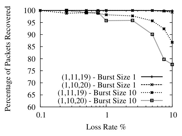
Figure 13: Relatively prime interleaves offer better performance
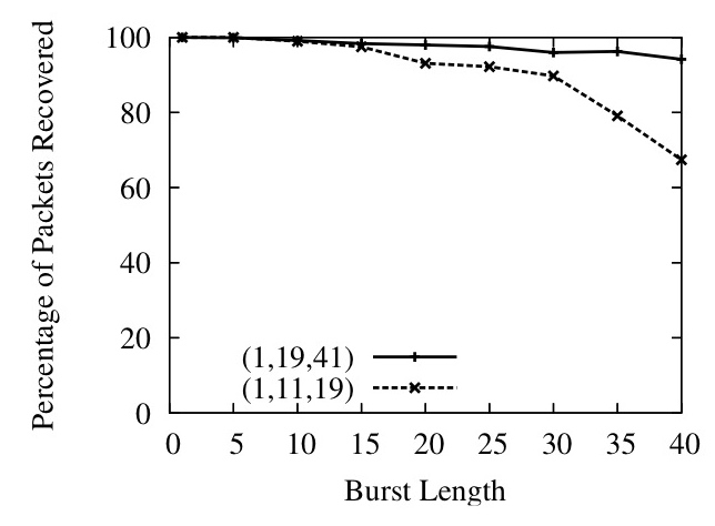
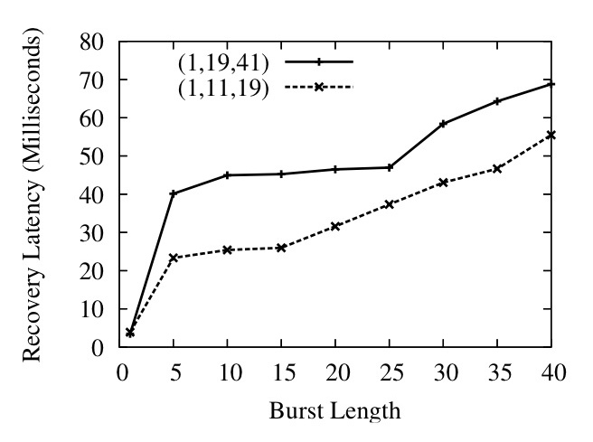
Figure 14: Layered Interleaving Recovery Percentage and Latency
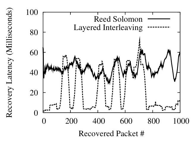
Figure 15: Reed-Solomon versus Layered Interleaving
Thus far we have shown how Maelstrom effectively hides loss from TCP/IP for packets dropped with uniform randomness. Now, we examine the performance of the layered interleaving algorithm, showing how different parameterizations handle bursty loss patterns. We use a loss model where packets are dropped in bursts of fixed length, allowing us to study the impact of burst length on performance. The link has a one-way latency of 50 ms and a loss rate of 0.1% (except in Figure 13, where it is varied), and a 10 Mbps flow of udp packets is sent over it.
In Figure 13 we show that our observation in Section 4.4 is correct for high loss rates - if the interleaves are relatively prime, performance improves substantially when loss rates are high and losses are bursty. The graph plots the percentage of lost packets successfully recovered on the y-axis against an x-axis of loss rates on a log scale. The Maelstrom configuration used is r=8,c=3 with interleaves of (1,10,20) and (1,11,19).
In Figure 14, we show the ability of layered interleaving to provide gracefully degrading performance in the face of bursty loss. On the top, we plot the percentage of lost packets successfully recovered against the length of loss bursts for two different sets of interleaves, and in the bottom graph we plot the average latency at which the packets were recovered. Recovery latency is defined as the difference between the eventual delivery time of the recovered packet and the one-way latency of the link (we confirmed that the Emulab link had almost no jitter on correctly delivered packets, making the one-way latency an accurate estimate of expected lossless delivery time). As expected, increasing the interleaves results in much higher recovery percentages at large burst sizes, but comes at the cost of higher recovery latency. For example, a (1,19,41) set of interleaves catches almost all packets in an extended burst of 25 packets at an average latency of around 45 milliseconds, while repairing all random singleton losses within 2-3 milliseconds. The graphs also show recovery latency rising gracefully with the increase in loss burst length: the longer the burst, the longer it takes to recover the lost packets. The Maelstrom configuration used is r=8, c=3 with interleaves of (1,11,19) and (1,19,41).
In Figures 16 and 17 we show histograms of recovery latencies for the two interleave configurations under different burst lengths. The histograms confirm the trends described above: packet recoveries take longer from left to right as we increase loss burst length, and from top to bottom as we increase the interleave values.
Figure 15 illustrates the difference between a traditional FEC code and layered interleaving by plotting a 50-element moving average of recovery latencies for both codes. The channel is configured to lose singleton packets randomly at a loss rate of 0.1% and additionally lose long bursts of 30 packets at occasional intervals. Both codes are configured with r=8, c=2 and recover all lost packets - Reed-Solomon uses an interleave of 20 and layered interleaving uses interleaves of (1, 40) and consequently both have a maximum tolerable burst length of 40 packets. We use a publicly available implementation of a Reed-Solomon code based on Vandermonde matrices, described in [36]; the code is plugged into Maelstrom instead of layered interleaving, showing that we can use new encodings within the same framework seamlessly. The Reed-Solomon code recovers all lost packets with roughly the same latency whereas layered interleaving recovers singleton losses almost immediately and exhibits latency spikes whenever the longer loss burst occurs.
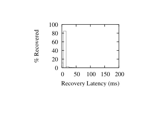
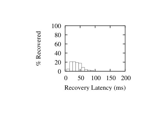
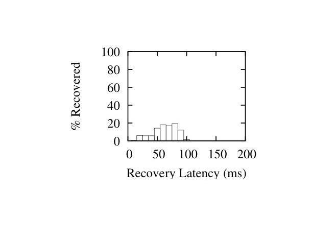
Figure 16: Latency Histograms for I=(1,11,19) - Burst Sizes 1 (Left), 20 (Middle) and 40 (Right)

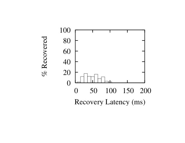
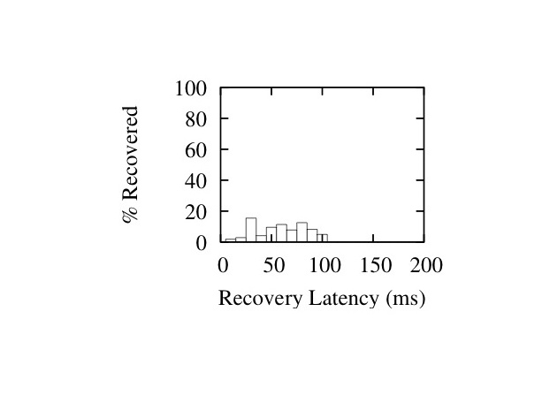
Figure 17: Latency Histograms for I=(1,19,41) - Burst Sizes 1 (Left), 20 (Middle) and 40 (Right)
6 Related Work
A significant body of work on application and TCP/IP performance over high-speed long-distance networks exists in the context of high-performance computing, grids and e-science. The use of parallel sockets for higher throughput in the face of non-congestion loss was proposed in PSockets [38]. A number of protocols have been suggested as replacements for TCP/IP in such settings - XCP [25], Tsunami [43], SABUL [13] and RBUDP [17] are a few - but all require modifications to end-hosts and/or the intervening network. Some approaches seek to differentiate between congestion and non-congestion losses [8].
Maelstrom is a transparent Performance Enhancing Proxy, as defined in RFC 3135[7]; numerous implementations of PEPs exist for improving TCP performance on satellite [42] and wireless links [9], but we are not aware of any PEPs that use FEC to mask errors on long-haul optical links.
End-host software-based FEC for reliable communication was first explored by Rizzo[37,36]. OverQOS [40] suggested the use of FEC for TCP/IP retransmissions over aggregated traffic within an overlay network in the commodity Internet. AFEC [34] uses FEC for real-time communication, modulating the rate of encoding adaptively. The use of end-host FEC under TCP/IP has been explored in [30].
A multitude of different FEC encodings exist in literature; they can broadly be categorized into optimal erasure codes and near-optimal erasure codes. The most well-known optimal code is Reed-Solomon, which we described previously as generating c repair packets from r source packets; any r of the resulting r+c packets can be used to reconstruct the r source packets. Near-optimal codes such as Tornado and LT [29] trade-off encoding speed for large data sizes against a loss of optimality - the receiver needs to receive slightly more than r source or repair packets to regenerate the original r data packets. Near-optimal codes are extremely fast for encoding over large sets of data but not of significant importance for real-time settings, since optimal codes perform equally well with small data sizes. Of particular relevance are Growth Codes [24], which use multiple encoding rates for different overhead levels; in contrast, layered interleaving uses multiple interleaves for different burst resilience levels without modulating the encoding rate.
The effect of random losses on TCP/IP has been studied in depth by Lakshman [28]. Padhye's analytical model [33] provides a means to gauge the impact of packet loss on TCP/IP. While most published studies of packet loss are based on the commodity Internet rather than high-speed lambda links, Fraleigh et al. [12] study the Sprint backbone and make two observations that could be explained by non-congestion loss: a) links are rarely loaded at more than 50% of capacity and b) packet reordering events occur for some flows, possibly indicating packet loss followed by retransmissions.
7 Future Work
Scaling Maelstrom to multiple gigabits per second of traffic will require small rack-style clusters of tens of machines to distribute encoding load over; we need to design intelligent load-balancing and fail-over mechanisms for such a scheme. Additionally, we have described layered interleaving with fixed, pre-assigned parameters, and the next step in extending this protocol is to make it adaptive, changing interleaves and rate as loss patterns in the link change.
8 Conclusion
Modern distributed systems are compelled by real-world imperatives to coordinate across datacenters separated by thousands of miles. Packet loss cripples the performance of such systems, and reliability and flow-control protocols designed for LANs and/or the commodity Internet fail to achieve optimal performance on the high-speed long-haul `lambda' networks linking datacenters. Deploying new protocols is not an option for commodity clusters where standardization is critical for cost mitigation. Maelstrom is an edge appliance that uses Forward Error Correction to mask packet loss from end-to-end protocols, improving TCP/IP throughput and latency by orders of magnitude when loss occurs. Maelstrom is easy to install and deploy, and is completely transparent to applications and protocols - literally providing reliability in an inexpensive box.
Acknowledgments
We would like to thank our shepherd Robert Morris and the other reviewers for extensive comments that significantly shaped the final version of the paper. Danny Dolev, Lakshmi Ganesh, T. V. Lakshman, Robbert van Renesse, Yee Jiun Song, Vidhyashankar Venkataraman and Vivek Vishnumurthy provided useful comments. Tom Boures provided valuable insight into the quality of existing fiber links, Stanislav Shalunov provided information on loss rates on Internet2, and Paul Wefel gave us access to TeraGrid loss measurements.
References
- [1]
-
Global crossing current network performance.
http://www.globalcrossing.com/network/network_performance_current.aspx.
Last Accessed Feb, 2008.
- [2]
-
Qwest ip network statistics.
http://stat.qwest.net/statqwest/statistics_tp.jsp.
Last Accessed Feb, 2008.
- [3]
-
Teragrid udp performance.
http://network.teragrid.org/tgperf/udp/.
Last Accessed Feb, 2008.
- [4]
-
Netfilter: firewalling, nat and packet mangling for linux.
http://www.netfilter.org/, 1999.
- [5]
-
Teragrid.
http://www.teragrid.org, 2008.
- [6]
-
M. Balakrishnan, K. Birman, A. Phanishayee, and S. Pleisch.
Ricochet: Lateral error correction for time-critical multicast.
In NSDI 2007: Fourth Usenix Symposium on Networked Systems
Design and Implementation, 2007.
- [7]
-
J. Border, M. Kojo, J. Griner, G. Montenegro, and Z. Shelby.
Performance Enhancing Proxies Intended to Mitigate Link-Related
Degradations.
Internet RFC3135, June, 2001.
- [8]
-
S. Bregni, D. Caratti, and F. Martignon.
Enhanced loss differentiation algorithms for use in TCP sources over
heterogeneous wireless networks.
In GLOBECOM 2003: IEEE Global Telecommunications Conference,
2003.
- [9]
-
R. Chakravorty, S. Katti, I. Pratt, and J. Crowcroft.
Flow aggregation for enhanced tcp over wide area wireless.
In INFOCOM, 2003.
- [10]
-
D. Comer, Vice President of Research and T. Boures, Senior Engineer.
Cisco systems, inc. Private Communication., October 2007.
- [11]
-
S. E. Deering and D. R. Cheriton.
Multicast routing in datagram internetworks and extended lans.
ACM Trans. Comput. Syst., 8(2):85-110, 1990.
- [12]
-
C. Fraleigh, S. Moon, B. Lyles, C. Cotton, M. Khan, D. Moll, R. Rockell,
T. Seely, and S. Diot.
Packet-level traffic measurements from the Sprint IP backbone.
IEEE Network, 17(6):6-16, 2003.
- [13]
-
Y. Gu and R. Grossman.
SABUL: A Transport Protocol for Grid Computing.
Journal of Grid Computing, 1(4):377-386, 2003.
- [14]
-
R. Habel, K. Roberts, A. Solheim, and J. Harley.
Optical domain performance monitoring.
Optical Fiber Communication Conference, 2000.
- [15]
-
T. Hacker, B. Athey, and B. Noble.
The end-to-end performance effects of parallel TCP sockets on a
lossy wide-area network.
In IPDPS, 2002.
- [16]
-
T. J. Hacker, B. D. Noble, and B. D. Athey.
The effects of systemic packet loss on aggregate tcp flows.
In Supercomputing '02: Proceedings of the 2002 ACM/IEEE
conference on Supercomputing, 2002.
- [17]
-
E. He, J. Leigh, O. Yu, and T. Defanti.
Reliable Blast UDP: predictable high performance bulk data
transfer.
IEEE International Conference on Cluster Computing, 2002.
- [18]
-
C. Huitema.
The case for packet level fec.
In PfHSN '96: Proceedings of the TC6 WG6.1/6.4 Fifth
International Workshop on Protocols for High-Speed Networks V, pages
109-120, London, UK, UK, 1997. Chapman & Hall, Ltd.
- [19]
-
J. Hurwitz and W. Feng.
End-to-end performance of 10-gigabit Ethernet on commodity systems.
Micro, IEEE, 24(1):10-22, 2004.
- [20]
-
Internet2.
End-to-end performance initiative: Hey! where did my performance go?
- rate limiting rears its ugly head.
http://e2epi.internet2.edu/case-studies/UMich/index.html.
- [21]
-
Internet2.
End-to-end performance initiative: When 99% isn't quite enough -
educause bad connection.
http://e2epi.internet2.edu/case-studies/EDUCAUSE/index.html.
- [22]
-
V. Jacobson.
Modified TCP Congestion Avoidance Algorithm.
Message to end2end-interest mailing list, April, 1990.
- [23]
-
L. James, A. Moore, M. Glick, and J. Bulpin.
Physical Layer Impact upon Packet Errors.
Passive and Active Measurement Workshop (PAM 2006), 2006.
- [24]
-
A. Kamra, J. Feldman, V. Misra, and D. Rubenstein.
Growth codes: Maximizing sensor network data persistence.
In Proceedings of ACM Sigcomm, Pisa, Italy, September 2006.
- [25]
-
D. Katabi, M. Handley, and C. Rohrs.
Congestion control for high bandwidth-delay product networks.
Proceedings of the 2002 conference on Applications,
technologies, architectures, and protocols for computer communications,
pages 89-102, 2002.
- [26]
-
D. Kilper, R. Bach, D. Blumenthal, D. Einstein, T. Landolsi, L. Ostar,
M. Preiss, and A. Willner.
Optical Performance Monitoring.
Journal of Lightwave Technology, 22(1):294-304, 2004.
- [27]
-
A. Kimsas, H. Øverby, S. Bjornstad, and V. L. Tuft.
A cross layer study of packet loss in all-optical networks.
In AICT/ICIW, page 65, 2006.
- [28]
-
T. Lakshman and U. Madhow.
The performance of TCP/IP for networks with high bandwidth-delay
products and random loss.
IEEE/ACM Transactions on Networking (TON), 5(3):336-350, 1997.
- [29]
-
M. Luby.
LT codes.
The 43rd Annual IEEE Symposium on Foundations of Computer
Science, 2002.
- [30]
-
H. Lundqvist and G. Karlsson.
TCP with End-to-End Forward Error Correction.
International Zurich Seminar on Communications (IZS 2004),
2004.
- [31]
-
P. Maymounkov and D. Mazieres.
Rateless codes and big downloads.
IPTPS03, 2003.
- [32]
-
J. Nonnenmacher, E. Biersack, and D. Towsley.
Parity-based loss recovery for reliable multicast transmission.
In Proceedings of the ACM SIGCOMM '97 conference, pages
289-300, New York, NY, USA, 1997. ACM Press.
- [33]
-
J. Padhye, V. Firoiu, D. Towsley, and J. Kurose.
Modeling tcp throughput: a simple model and its empirical validation.
SIGCOMM Comput. Commun. Rev., 28(4):303-314, 1998.
- [34]
-
K. Park and W. Wang.
AFEC: an adaptive forward error correction protocol for
end-to-endtransport of real-time traffic.
Computer Communications and Networks, 1998. Proceedings. 7th
International Conference on, pages 196-205, 1998.
- [35]
-
M. Reardon.
Dark fiber: Businesses see the light.
http://www.news.com/Dark-fiber-Businesses-see-the-light/2100-1037_3-5557910.html?part=rss&tag=5557910&subj=news.1037.5, 2005.
Last Accessed Feb, 2008.
- [36]
-
L. Rizzo.
Effective erasure codes for reliable computer communication
protocols.
SIGCOMM Comput. Commun. Rev., 27(2):24-36, 1997.
- [37]
-
L. Rizzo.
On the feasibility of software FEC.
Univ. di Pisa, Italy, January, 1997.
- [38]
-
H. Sivakumar, S. Bailey, and R. L. Grossman.
Psockets: the case for application-level network striping for data
intensive applications using high speed wide area networks.
In Supercomputing '00: Proceedings of the 2000 ACM/IEEE
conference on Supercomputing (CDROM), page 37, Washington, DC, USA, 2000.
IEEE Computer Society.
- [39]
-
Slashdot.com.
Google's secret plans for all that dark fiber.
http://slashdot.org/articles/05/11/20/1514244.shtml, 2005.
- [40]
-
L. Subramanian, I. Stoica, H. Balakrishnan, and R. H. Katz.
Overqos: An overlay based architecture for enhancing internet qos.
In NSDI 04: First Usenix Symposium on Networked Systems Design
and Implementation, 2004.
- [41]
-
A. Tirumala, F. Qin, J. Dugan, J. Ferguson, and K. Gibbs.
Iperf-The TCP/UDP bandwidth measurement tool.
http://dast. nlanr. net/Projects/Iperf, 2004.
- [42]
-
D. Velenis, D. Kalogeras, and B. Maglaris.
SaTPEP: a TCP Performance Enhancing Proxy for Satellite Links.
Proceedings of the Second International IFIP-TC6 Networking
Conference on Networking Technologies, Services, and Protocols; Performance
of Computer and Communication Networks; and Mobile and Wireless
Communications, pages 1233-1238, 2002.
- [43]
-
S. Wallace et al.
Tsunami File Transfer Protocol.
In PFLDNet 2003: First Int. Workshop on Protocols for Fast
Long-Distance Networks, 2003.
- [44]
-
P. Wefel, Network Engineer.
The University of Illinois' National Center for Supercomputing
Applications (NCSA). Private Communication., Feb 2008.
- [45]
-
B. White, J. Lepreau, L. Stoller, R. Ricci, S. Guruprasad, M. Newbold,
M. Hibler, C. Barb, and A. Joglekar.
An integrated experimental environment for distributed systems and
networks.
In Proc. of the Fifth Symposium on Operating Systems Design and
Implementation, Boston, MA, 2002.
- [46]
-
S. Wicker and V. Bhargava.
Reed-Solomon Codes and Their Applications.
John Wiley & Sons, Inc. New York, NY, USA, 1999.
Footnotes:
1Rateless codes (e.g, LT codes [29]) are increasingly popular and used for applications such as efficiently distributing bulk data [31] - however, it is not obvious that these have utility in real-time communication.
File translated from
TEX
by
TTH,
version 3.80.
On 19 Feb 2008, 23:46.