
| ||||||||||||||||||||||||||||||||||||||||||||||||||||
|
MobiSys '05 Paper
[MobiSys '05 Technical Program]
WALRUS: Gaetano
Borriello1,2, Alan Liu1, Tony
Offer1, Christopher Palistrant1, Richard Sharp3 1Department of Computer Science and
Engineering, 2Intel Research Seattle, 3Intel Research {gaetano@cs.washington.edu} Abstract In this paper, we propose a system
that uses the wireless networking and microphone interfaces of mobile devices
to determine location to room-level accuracy. The wireless network provides a
synchronizing pulse along with information about the room. This is accompanied by an ultrasound beacon
that allows us to resolve locations to the confines of a physical room (since
audio is mostly bounded by walls). We generate the wireless data and ultrasound
pulses from the existing PCs in each room; a PDA carried by a user listens for
both signals. Thus, our approach does not require special hardware. We do not
use ultrasound to send data. As a result we dramatically reduce the
computational burden on the mobile device while also decreasing the latency of
location resolution. Our results indicate that (i)
ultrasound detection is robust even in noisy environments with many
reflective surfaces; and (ii) that we can determine the correct room within a
couple of seconds with high probability even when the ultrasound emitting PCs
are not synchronized. 1. INTRODUCTION
Future mobile devices will need the ability to determine their location and, thus, enable location-enhanced computing. Location is a major part of a user’s context and applications can be constructed that adapt to the user’s current location. For example, a calendar reminder system can adapt by adjusting the time of an alarm based on traffic conditions or public transportation options between the user’s current location and their next destination. Applications can be designed that record the current location so as to better classify data for future retrieval. For example, a digital camera can record the location at which each picture was taken. Location can also be used to modify the behavior of existing applications. For example, a web browser can be set up to automatically render web pages associated with the user’s current location. The Global Positioning System ( Many systems have been designed to provide mobile devices with the capability to monitor their location indoors (some of these will be discussed in detail in the next section and a more complete bibliography can be found at: http://binary.engin.brown.edu/publication/ Positioning_Ref.pdf). Designers of these location systems need to make several key tradeoffs that affect the system’s usability [5, 7], among these are: ·
Affordability.
A
location system should be a minute fraction of the total cost of a mobile
device. Cost includes not only the final
monetary cost to individual users, but also the cost associated with
installation, management, and maintenance of the infrastructure portion of the
system. ·
Resource
Requirements. Mobile devices have limited memory, computational capabilities, and
power; the need to accommodate expensive computations not only adds extra cost
to the system but also makes it less usable if it shortens battery life. ·
Privacy. A system
that requires a user or mobile device to query a server or host for a location
will need to reveal the user’s identity in exchange for this information. This may be considered an undesirable feature
for users who wish to remain anonymous. Moreover, the infrastructure-based
supplier of this information may charge the user for this service thereby limiting
the number of applications and/or their frequency of location updates. With careful design, a system can be devised
where a user receives information that helps determine their location without
potentially revealing confidential information or even their presence. ·
Portability. Mobile
systems are an evolving technology and some consideration should be given to
ensure that a system can be easily maintained during upgrades and across most
platforms. To ensure that a system is readily adopted and maintained across
several generations of hardware, a location system should consider how and if
the system will be able to adapt to future technologies. ·
Precision. Designers
must decide what degree of precision a location system will provide. Precision is defined as the granularity that
a system is capable of measuring. Many location systems have been developed
with precisions ranging from centimeters to kilometers. For many ubiquitous
computing applications, room-level accuracy is an important grain size as it
closely relates to the places people often think about. Usually, higher levels of precision correlate
strongly with increased cost of the location system. ·
Accuracy. Designers
of location aware systems consider accuracy to be the percentage of the time a
known level of precision is reached. For
example, a Based on these design factors, many different types of systems can be developed that will meet a variety of unique criteria in the available design space. This paper describes, WALRUS, a location system that emphasizes: low cost, high privacy, high portability, room-level precision, and high accuracy. A key design feature of WALRUS is that it leaverages existing hardware. The WALRUS client can run on any device that can receive WiFi packets and listen to ultrasound (at approximately 21KHz). These capabilities are found in most modern laptops, tablets, and PDAs that usually include integrated WiFi and microphones/speakers. Furthermore, they are likely to make their way into even more devices, such as cell phones and wrist-watches, in the near future with the advent of low-power radio protocols such as 802.15.4 (Zigbee) and ultra-wide-band (UWB). Section 2 of this paper discusses several other location systems that share similarities with the WALRUS system, but as will be seen later, exhibit important differences as well. Section 3 describes the implementation of WALRUS. Section 4 details the results of our experiments and evaluates how well the system worked. Finally, Section 5 outlines future work that can be done to improve the WALRUS systems and how it may evolve. 2. RELATED
|
|
System |
Privacy |
Client cost |
Infrastructure cost |
Precision |
Operational Scope |
|
WALRUS |
Client devices compute location |
No additional hardware |
PC per room + WiFi |
room-level |
Indoor |
|
|
Client devices compute location |
Approx. USD100 receiver |
Satellite network |
1-5m |
Outdoor |
|
Place Lab |
Client devices compute location |
No additional hardware |
WiFi, GSM, and/or Bluetooth beacons |
15-30m |
Outdoor/Indoor |
|
Radar |
Client devices |
No additional hardware |
WiFi coverage |
5m |
Indoor |
|
ActiveBadge |
Central server tracks clients |
Low-cost badge |
Badge IR receivers |
room-level |
Indoor |
|
CoolTown |
Client devices |
IR transceiver |
IR transmitter on all objects of interest |
3-5m IR |
Indoor |
|
Active Bat |
Central server tracks clients |
Low-cost bat |
Ultrasound receivers in ceiling |
5-10cm |
Indoor |
|
Cricket |
Client devices compute location |
Low-cost client ultrasound rcvr |
Ultrasound transmitters |
1 m2 region |
Indoor |
|
E911/E112 |
Central server tracks clients |
No additional hardware |
Cellular network |
100m |
Outdoor/Indoor |
|
Table 1. Summary of location sensing systems. |
Like
Radar [1] is an earlier example of Place Lab’s approach that required a calibration process for the client device. Although it achieved resolution on the order of 5m when finely calibrated it suffers from similar limitations as Place Lab.
ActiveBadge does not provide
absolute coordinates like
HP’s CoolTown [13] adds IR transmission capability to objects/appliances of interest. Client devices hear objects’ URLs and can access web pages to control the objects or find out more about them. CoolTown also requires line-of-sight between client and object and requires a database of object positions to enable localization.
The ActiveBat system is similar to the ActiveBadge system in architecture. However, ActiveBats use radio-synchronized ultrasound instead of infrared and provide a higher level of precision. ActiveBat-enabled devices emit a pulse of ultrasound when prompted via radio by the infrastructure and are localized in three dimensions within a room, by the centralized system, using measurements from time-of-flight calculations to various ultrasound receivers scattered throughout the room (usually in the ceiling) [4]. The ActiveBat infrastructure is costly both to purchase and to install (requiring detailed surveying of each receiver’s position). Once Active Bat is set up, however, it is capable of locating devices with near-centimeter precision. In contrast, WALRUS provides a much more coarse-grained precision than ActiveBat, but WALRUS can also be decentralized, unlike ActiveBat, and can support a larger number of users because no coordination is required among all the clients, only among the emitters which are bounded by the infrastructure. The information concerning the location of the ActiveBat devices is managed by a central server, thus greatly reducing the privacy-friendliness of the ActiveBat system. This coordination is essential in guaranteeing efficient use of the available ultrasound bandwidth among all the client devices that must emit sound to be positioned. ActiveBats, like WALRUS must operate indoors for the ultrasound receivers to be effective.
The Cricket location system, unlike either ActiveBat or ActiveBadge, emphasizes a lack of dependence on a centralized structure to implement a complete positioning system. The Cricket system uses fixed beacons with known coordinates to emit ultrasound pulses that are used by mobile receivers to estimate position through time-of-flight calculations [8, 10]. Cricket is decentralized like WALRUS, so it preserves privacy by performing location calculations directly on the mobile clients. However, unlike WALRUS, which utilizes pre-existing hardware, Cricket requires the purchase and installation of special beacons and receivers. Once Cricket’s infrastructure is established in an indoor environment, the system provides positioning precision to within 1m2 regions within a room (since the ultrasound does not travel through walls).
Finally, E911/E112 systems being developed for cellular
phones are another ubiquitous location technology. They are being mandated by governments to
help locate the originators of emergency phone calls. These systems rely on cell service providers’
ability to triangulate from their cell towers to individual phones. Therefore, the infrastructure computes the
location and provides it to emergency services or the user, often for a fee,
thereby potentially limiting the applications that will take advantage of this
capability. The precision of this
approach is much less than
Table 1 summarizes the previous discussion of existing
location sensing technologies. The
positioning systems WALRUS,
WALRUS is a distinct point in the space of possible
positioning systems. It draws different
components and ideas from other positioning systems but employs a unique
mixture of these elements to achieve its goals.
Place Lab and Radar provide the idea of using pre-existing technology to
reduce cost: Cricket and
Like the Cricket positioning system, WALRUS uses ultrasound beacons to provide mobile devices with the opportunity to determine their location. However, WALRUS requires no additional hardware. Standard desktop speakers are used to transmit ultrasound and typical PDA/laptop microphones to receive it. In addition, WALRUS uses 802.11 communication as the information-bearing channel (via broadcast UDP datagrams) rather than a specialized radio.
In [6], the use of common computing hardware is used to readily transmit and receive ultrasonic signals without intrusive human obstruction. Unlike [6], WALRUS does not send data in the ultrasound signal – this radically reduces computational requirements and decreases resolution latency. The ultrasound sources do not need to be coordinated and there can be more than one to better cover larger rooms (those significantly more than 10m in any dimension).
As one of the key design considerations of WALRUS is to use preexisting hardware for positioning purposes, all major components of the system reside in software. WALRUS is implemented in Java in order to aid in the portability of the system across an array of constantly evolving mobile technologies. Two main components comprise the WALRUS system: the server-side beacon software and the mobile client software.
A server beacon runs as a desktop PC with attached speakers (most standard speakers easily produce sound in the range we are interested in – around 21KHz); it provides ultrasound for the mobile devices to receive and can send 802.11 packets to access points (APs) in the infrastructure for broadcasting (alternatively, if the PC has a wireless networking capability, it can broadcast the packet itself, but this is not a requirement). A mobile client must have an integrated microphone (such as most PDAs, laptops, and tablets as well as cell phones) that can discern the presence of an ultrasound signal (most mobile device microphones can easily do this) and must be able to receive 802.11 broadcast packets through typical WiFi cards.
The 802.11 packets are broadcast by APs and, depending on how the wireless network (WLAN) is configured, may be heard in an area much larger than that covered by a single room. This will limit the rate at which localization events can occur for each room. For client devices to hear these broadcast packets, they need to be in “monitor mode” (that is, not associated with a specific AP for a network connection). Therefore, currently, we can’t localize while the user is communicating over the network and vice-versa. However, there is no technical reason this problem is not surmountable. Only minor software changes to the APs and wireless interface drivers are needed. This is consistent with a model of ubiquitous broadcast computing advocated in [12].
When initiated, the server software begins by opening and parsing a simple file that contains a description of the room where the server is actually located. The contents of the file can easily be modified to include simple room attributes, such as the name of the room, the amenities available, who to contact in case of inquires, URLs to relevant web pages, etc. The contents of the room description file are packaged into an 802.11 datagram packet. The server periodically (with some random variation to avoid collisions with nearby servers) broadcasts the room’s data packet (either directly or through an AP) simultaneously with a short audio signal at 21KHz. Of course, an appropriate speaker must be present on the server in order for it to broadcast the ultrasonic signal (a typical desktop PC with typical speakers does just fine – there are no special sound card requirements).
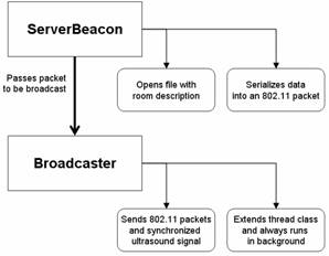
Figure 1. The ServerBeacon system runs on a desktop PC with typical speakers.
Because no data is transmitted in the ultrasound there is no need to dynamically modulate the sound wave. As a result, the ultrasonic signal can be pre-generated once and stored in any number of audio formats. After experimenting with several different methods for ultrasonic generation, we discovered that a utility called sox, was ideal for this purpose. Additionally, the amplitude of the audio signal is linearly increased and decreased at the beginning and end of playback, respectively. This ramping method creates a trapezoidally-shaped envelope for the amplitude of the sound and effectively band-limits the signal, avoiding the generation of audible clicks at the edges of the pulse.
Figure 1 graphically describes the hierarchical overview of the server software. In Java code, a ServerBeacon object instantiates a Broadcaster object after opening and parsing the appropriate room description file. The Broadcaster is responsible for periodically sending both the ultrasonic signal and 802.11 packet. Broadcasting time is randomized on the server to minimize the possibility of two separate servers interfering.
A further optimization, which we have not yet implemented, is to coordinate the servers so that they take explicit turns in broadcasting their data. This time-multiplexing scheme is employed by ActiveBats [4] where a round-robin schedule is used to serialize each Bat’s ultrasound pulse. This approach limits the rate at which localization events can be accomplished but decreases the chance of collisions making the system more robust and more likely to make use of each ultrasound pulse. Furthermore, the system can be further optimized to exclude empty rooms, detected by motion sensors, from the schedule.
The task of the mobile client software is to listen for 802.11 location description packets and then listen for a corresponding ultrasound pulse. Of course, the device may hear multiple 802.11 packets as RF travels through walls but it should only hear ultrasound from speakers in the same room.
Currently, the mobile client software requires the mobile device to have basic recording capabilities and either a floating point processor or floating point emulation instructions. Common mobile devices used throughout the design and development of the WALRUS system include a Dell Inspiron 8200 laptop with a 2.2GHz Mobile Pentium 4 processor and an HP iPAQ 3870 with a 206MHz StrongArm processor both running Linux operating systems. Although these are highly capable systems, we do not see obstacles to transforming our computation to fixed point arithmetic so that it can be performed on less capable devices.
While it does take longer for WALRUS to execute on mobile devices that have only floating point emulation rather than those that use a true floating point processor, we discovered that we were able to minimize the delay due to floating point emulation on an HP iPAQ 3870 by performing the instructions in a software pipelined fashion.
The mobile client component is designed to run whenever it hears an 802.11 location packet. It records audio from the microphone for enough time for a typical room size (e.g., 50-100ms can handle a good sized room of 18m maximum dimension at 25°C). It then looks for energy in the received audio in a small band around 21KHz. If there is a signal there, then it is likely the device is in the room that generated the last location information-bearing 802.11 packet. Conversely, if there is no energy at 21KHz, then it is likely that the device is in a different room. Several readings over a few seconds can quickly provide a high-confidence room-level location estimate. Note that the client device only expends energy on ultrasound detection when it hears an 802.11 location packet. The rest of the time, it performs no ultrasound calculations at all.
The MobileClient class is responsible for instantiating the correct objects to detect 802.11 packets and ultrasonic signals, as well as maintaining a probabilistic location analysis based on the positive detection of ultrasonic and datagram signals. The MobileClient ultimately provides location information to the granularity of a room inside a building based on the reception of 802.11 broadcasts and the corresponding detection of the paired ultrasound pulse.
The room information is in a form deemed appropriate by whoever setup the ServerBeacon in that room. We expect typical information to include: room number, floor, organization to whom the room belongs, phone number for facilities personnel, optionally encrypted occupant information, URLs to web pages describing aspects of the room, etc. For example, a conference room in our department could broadcast: that it is room 403; it is on the 4th floor of the Allen Center; that the building is the Paul G. Allen Center at the University of Washington; a URL to a page with links to the department’s home page, building directory and floor-plan, sign-up calendar for the room; the IP address of a projector available for presentations, the IP address of a large flat panel display, and instructions on how to connect to a guest wireless network.
Also written in Java for portability, the Mobile Client software is comprised of two main components: a DatagramListener (for room information packets) and an UltrasoundListener (see Figure 2).
As already mentioned, the client can’t do localization at the same time
as it is communicating over the network for data transfers (e.g., web
browsing). The current limitations of
wireless cards and APs require two incompatible modes
of operation: monitor mode for listening to broadcast packets anonymously
without requiring association to an AP (we do not want to require association
for reasons of preserving anonymity for clients); and infrastructure mode for
two-way networking with AP association a required part of this mode.
The DatagramListener is a thread that continuously receives UDP packets through the 802.11 wireless protocol and forwards these messages, which contain room-identifying information, to the MobileClient. The DatagramListener initializes a multicast socket and waits until it receives a datagram packet. Upon reception of a message, the packet is time stamped and the MobileClient is notified of an available packet for interpretation.
Once a MobileClient receives notification from the DatagramListener that a message has been received, the message is added to a data structure in the MobileClient object that allows later association and probability analysis. The MobileClient then waits for positive ultrasonic detection by the UltrasoundListener. The amount of time to wait is dependent on the size of the room – this data can also be broadcast in the location information packet over 802.11 so that each room provides its own customized timeout interval.
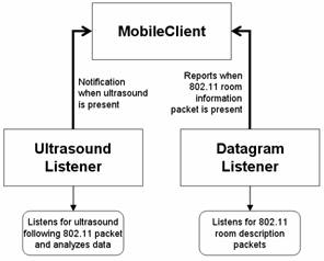
Figure 2. A MobileClient consists of two main parts: an UltrasoundListener and a DatagramListener.
The UltrasoundListener thread continuously records audio in the specified interval after the 802.11 datagram is received and notifies the MobileClient when it detects ultrasound. The MobileClient object attempts to correlate the datagram messages with the ultrasound detections in order to find the best match that will provide an accurate room determination. In the Java code, an UltrasoundListener is a thread that acquires an available microphone interface to be used for recording ultrasonic signals and instantiates a pool of UltrasoundAnalyzer threads, which are later used in calling and evaluating the captured audio signals.
The UltrasoundAnalyzer thread has a method called available() which is used by the UltrasoundListener object to determine whether there are available analyzer threads ready to receive data. Analysis of recorded audio data begins after data is available and the analyze() method of an UltrasoundAnalyzer is called. Once the analysis is complete, the UltrasoundAnalyzer thread signals the UltrasoundListener object, records the time if ultrasound was detected and becomes available to analyze another set of data.
The UltrasoundDetector object is responsible for calling an appropriate digital signal processing algorithm. WALRUS currently uses the Goertzel algorithm because, similar to a narrow bandpass filter, it is useful when analyzing a signal for energy in a small band centered on a particular frequency. Additionally, the Goertzel algorithm has several optimizations that allow for very quick computations [2].
The UltrasoundDetector object instantiates three instances of the Goertzel algorithm in order to compare the relative magnitudes of the desired ultrasonic frequency to two adjacent frequencies: one above and one just below 21KHz. Since white noise contains a wide variety of similar frequencies, we can largely eliminate the possibility of detecting unwanted ultrasonic sounds by ensuring that the relative magnitude of the 21KHz frequency is much greater than the relative magnitudes of signals with frequencies just above and below 21KHz. Prior to using three instances of the Goertzel algorithm, false positives were often detected when the doors shut or the detecting microphone heard a whistle or jingling keys. However, once three Goertzel algorthim instances were used by the UltrasoundDetector, no false positives were detected during any of the remaining tests.
The MobileClient manages a data structure that keeps a running history of the 802.11 packets received. After the MobileClient class has been notified of an ultrasonic detection, analysis must be done to match the ultrasonic detection with an 802.11 packet and derive a probability that the two signals are coupled.
Upon detecting ultrasound, the data structure storing 802.11 packets is examined to determine if at least one 802.11 packet has arrived within the Maximum Detection Time. The Maximum Detection Time defines the time interval to be examined. It is determined from the 802.11 packet reception time and the amount of time it specifies to wait for its corresponding room. If only one 802.11 packet is received within the Maximum Detection Time period, then this 802.11 packet is easily associated with the ultrasound signal. If more than one 802.11 packet is present then the ADT, the Average Detection Time, is used to make a decision. The ADT is a value derived from historical data for the current room. It provides some hysteresis to changes in room estimates.
Figure 3 describes the process of associating an ultrasonic signal and 802.11 datagram. In the figure, 802.11 packets from Rooms A, B, and C are considered because they all fall within the Maximum Detection Time range. That is, they may have been the packets associated with the ultrasound signal that was detected. We consider the difference in time between the detected ultrasound and each of the packets received. In the case of Figure 3, the packet for Room C has the smallest difference between its arrival time and the ultrasound detection. We then compare these differences against the current ADT. Since the difference between the ultrasound detection event and the packet for Room B is the closest is value to the current ADT, we associate this ultrasound signal with Room B. This may be wrong and is likely to be corrected when the next round of packets are broadcast as they are probabilistically very unlikely to cause similar confusion. Finally, the ADT for the current room is updated by averaging in this latest detection time difference.
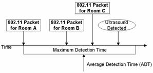
Figure 3. After ultrasound detection, the
previous 802.11 messages received are analyzed to
determine the most likely match using an average detection time (ADT) derived
from recent history.
WALRUS has proven itself to be a robust system for determining room location. Our tests have shown that it provides accurate and consistent localization with room-level resolution. Anyone carrying a mobile device enabled with WALRUS in a WALRUS-enabled space can walk from room to room and determine their location via the mobile device.
Since the WALRUS-enabled mobile device is able to determine its room location in terms meaningful to a person, it can use this information to provide details about nearby services to the user. An external application could be constructed containing a database of known services and their locations on a virtual map. Once the mobile device learns its position on the virtual map, it would be able to determine what services are nearby and provide navigation descriptions that include hallways, intersections, and other landmarks that can be much more meaningful and effective for people as opposed to simple Cartesian distances.
Attempting to use readily-available technology as a foundation for our system has also proven to be a valid endeavor. Anyone who wants to equip an office building with location technology needs only to install and run our server beacon software on a speaker-equipped desktop system in each room of interest, utilize likely pre-existing WiFi access points, and install and run our mobile client software on a microphone-equipped mobile device of choice. No additional setup or hardware is required for our system.
As a tradeoff to its high degree of reliability, WALRUS suffers slightly from slow performance. Most of this delay is used to increase accuracy as well as reliability. For example, the period of time between server beacon broadcasts must be large enough so that the chances of nearly simultaneously received messages are reduced. For a typical office scenario, we can assume rooms on the order of 25m2 and that the ultrasound may travel twice the length of the room to ensure reflections die out. This 10m distance is traversed in approximately 30msec at 20ºC. If we assume a 10msec ultrasound pulse, this allows us to realize 25 (1/(.030+.010)) localization events per second if we schedule each room to fire its beacon packet in turn. If we assume that a typical WiFi AP has a range of 50m and, therefore, covers approximately 100 of our 25m2 rooms, then we can localize every 4 seconds. Even though this estimate is somewhat pessimistic as significant space is occupied by hallways and many APs have reduced range through several walls, we feel it is a reasonable rate to expect from WALRUS in practice.
A history of recent room determinations can be kept on the client and used to calculate relative probabilities for room locations so that incorrect room determinations do not immediately cause the mobile device to believe that it is in a different room. However, this increases the amount of time it takes for the mobile client to change its belief in a given room location when moving between rooms because multiple identical room determinations must occur before the mobile client indicates a large enough confidence that it has changed rooms. Experimentation is needed to determine the best values for some of these parameters.
The system as it currently exists is not well suited for interactive map applications since the mobile device’s position on a virtual map would be perceptibly skewed in time from its actual physical location. It could take several seconds for the mobile device’s position on the virtual map to update once the mobile device crosses a room boundary. WALRUS is better suited for non-interactive location awareness in devices that move at human speeds from room to room or that do not need immediate location resolving. For example, WALRUS could be used to help mobile devices connect to infrastructure resources in a particular room (e.g., a smart conference room). WALRUS could also benefit someone who occasionally moves from office to office during the day but who enjoys the benefits of certain location-aware applications on his mobile device. WALRUS is particularly useful for mobile workers who reach a new location and need access to local information.
Though relatively slow, WALRUS does offer accurate ultrasound
detection, the critical element for an accurate room determination. According to our tests, the mobile client,
consisting of a Dell Inspiron 8200 laptop with built-in microphone, is able to
correctly detect ultrasound with little error across distances up to
approximately 13 meters. WALRUS is able
to achieve this because there is no data to decode in the ultrasound
signal. In [3], it was shown that is was
not possible to transmit data reliably at 18.4KHz over
standard speakers/microphones. In [6],
only 95% of packets were decoded correctly over ultrasound at 21KHz even over distances as short as 1-1.5m. Also, in [6], it was shown that it took
approximately 15 seconds to transmit an 8-bit room identifier over ultrasound
because the signal-to-noise ratio (
In order to test our system’s ultrasound detection reliability, we used our server beacon code (running on a Dell Inspiron 600m notebook computer) to broadcast a 10 ms ultrasound pulse at regular intervals from a standard, cheap pair of desktop speakers (Altec Lansing ADA215). We then used our mobile laptop device (Dell Inspiron 600 notebook computer) to execute our mobile client software at varying distances from the server beacon’s speakers. We examined the times at which ultrasound was received on the laptop and tried to correlate these with the regular intervals at which ultrasound was being broadcast. Long periods of time between ultrasound detections were noted as missed detections and short periods of time between ultrasound detections were noted as false positive detections. This set of tests was performed in a computer laboratory environment, filled with both the ambient noise of people working and various shelves and racks that could interfere with the transmission of ultrasound – an environment not advantageous to our approach (see Figure 4 for a photograph of the lab in which the tests were conducted – notice the large metal benches providing many surfaces for ultrasound reflections). The results of these tests are shown in Figure 5.
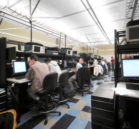
Figure 4. Laboratory environment for our initial tests.
The percentage of the time that ultrasound was detected when ultrasound was actually present, as well as the percentage of time that ultrasound was detected when ultrasound was not present, is given at various distances from the server beacon. The graph shows that correct ultrasound detection occurs nearly one hundred percent of the time up until about 10 meters away from the server beacon, it drops off sharply after that point. However, it is anticipated that most rooms used to contain WALRUS server beacons will not be so large; such expansive rooms would most likely require multiple sound sources for the same room information. The chart also shows that false positive detections of ultrasound occur anywhere from zero to three percent of the time and become more noticeable only when the distances are greater. It is possible that the false positive ultrasound detections are caused by delayed ultrasonic sound waves arriving at the laptop through different paths than the direct one traversed by most of the ultrasonic energy. As these findings show, WALRUS is effective at detecting ultrasound at distances up to about 10m – a good distance for most rooms in an office building.
Figure 5. Results of ultrasound detection experiments.
We also performed a variety of trials to determine if common environmental noise would cause the mobile client to detect ultrasound when it was not sent by the server. For these tests we used a typical office in our building that includes whiteboard partitions, book shelves, and many desk surfaces (see Figure 6). The office is 5m by 7m.
In the first trial, the mobile client was placed next to three people in an office having a conversation at normal volume. In the second trial, a variety of MP3- and Ogg Vorbis- encoded music, including Jazz, Rhythm and Blues, Alternative, Classic Rock, and Techno, were played through the server's speakers placed 5ft from the client. In the third trial, the client was left running over two days in an office, while events such as doors slamming, keys jingling, people talking, and cell phones ringing occurred. No ultrasound was detected during any of the trials.
To see whether loud noise affects ultrasound detection, the above musical selections were played on a separate speaker next to the client while the server generated ultrasound pulses. No difference in accuracy of ultrasound detection was observed. The results were not significantly different even in the presence of vertical whiteboards extending to 5 feet in height. The parameter that most affected the results was the orientation of the speakers to the client. The best case is when the client is directly facing the speakers, there is a noticeable drop-off in detection precision after 10m when the client is at 90º to the speakers. However, this distance is greater than the dimensions of the rooms of interest to us. This gives us confidence that our approach can be quite robust and highly accurate in typical office environments.
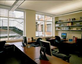
Figure 6. Office environment similar to that used for our tests.
We also did tests that varied the volume of the speakers to see if we could control “leakage” of the ultrasound out of an open doorway. We tried 5 different volume positions corresponding to Windows XP’s 20%, 40%, 60%, 80%, and 100%. We felt this was a reasonable, if imprecise experiment as this is the setting most users will adjust on their office PCs and we wanted to reflect that is likely to happen in practice. Within the office, ultrasound detections were almost perfect at all levels for distances up to 5m. We noticed a drop in detection accuracy (down to 88%) at the 20% setting at 5m distance. Leakage out of the office door is shown in the two parts of Figure 7. On the left, the speakers are oriented are far from the door and the two curves show detection of 20% and 40% settings. On the right, the speakers are near the door and the volume is set to 20%.
We can see that it is practical to have the speakers set at a low volume in most office settings so that leakage is confined to the area immediately outside the door. Even if the client is outside the office, this location determination is likely to be appropriate for hallways.
The certainty with which WALRUS makes room determinations is dependent on the number of room location messages that the system is receiving. Since WALRUS attempts to correlate the times that it received ultrasound with the times that it received room location messages, the occurrence of several room location messages in close time proximity makes it difficult for the system to choose the best pairing of 802.11 messages and ultrasound detections.
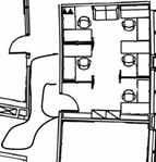
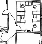
Figure 7. Leakage of ultrasound past office door for two different positions of the speakers (shown as two triangles).
In order to make quantitative assessments about WALRUS’ ability to correctly determine room locations, we set up varying numbers of server beacons to broadcast different room messages. Each of these server beacons was located in the same room and used the same AP to broadcast its location description packet, but only one of the beacons was equipped with standard desktop speakers for broadcasting ultrasound. Every time the mobile client correctly determined that it was in the room described by the room message from the beacon with speakers, this was noted as a correct room determination. Every time the mobile client determined that it was in the room described by the room message from one of the other beacons, this was noted as an incorrect room determination. The results of these tests with varying numbers of server beacons are given in Figure 8.
This chart shows the percentage of time that the mobile client correctly correlated ultrasound detection with the room message being broadcast by the beacon with speakers. As seen in the chart, WALRUS has near-perfect location determination with only two server beacons running – as one might expect, the chance of collisions is low. However, this accuracy drops as the number of beacons using the same AP increases. With six server beacons running, the mobile client is only able to correctly determine room location about 84% of the time. In order to view the trend of decreasing accuracy for larger numbers of server beacons, this test was also run with 25 server beacons broadcasting different room messages. As the chart shows, this large number of beacons within range of the mobile client causes the accuracy in room determination to drop below 50%. Thus, it can be seen that WALRUS’s ability to correctly correlate ultrasound with received room messages drops steadily as the number of running server beacons within range of the mobile client increases. Use of historical data provides some smoothing that corrects many of these errors at the cost of some further latency in room determination.
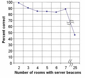
Figure 8. Room determination reliability with varying numbers of server beacons.
In order for WALRUS to be an effective indoor positioning system, the number of location description messages received by mobile clients from nearby server beacons can be reduced fairly easily by limiting the server beacons to broadcast UDP packets only through their local WiFi AP so that the number of beacons heard in a region is reduced to the minimum. In fact, we envision a basic device that can be left in a room (or connected to a PC) with a purposely short-range WiFi transceiver and an ultrasound-optimized speaker. Such a package could easily cost on the order of USD20 and be very trivial to configure – it simply needs a room information packet and transmission period with dynamic information available from a central server that sends packets to all of these units. Each can pick out the information relevant to its room. In this manner, we would expect to reduce the number of server beacons that can be confused by a client to only a few. Two or three localization events (8 to 12 seconds) then provide a high probability of a correct room determination. More importantly, such a specialized device obviates the need to keep a PC running in every room and could be made small enough to just fit into an electrical outlet, light switch, or even light bulb socket.
The WALRUS positioning system suffers slightly from slow performance, but it is highly reliable and accurate in office-scale environments. It is useful for all the situations in which we initially anticipated it being used. WALRUS is definitely not perfect. There are several tuning parameters to be experimented with and there is still a great deal of work that could be done to make it faster and more expandable to larger-scale environments with more densely packed rooms.
Several options exist for future work to improve the
WALRUS system. One key feature that
still needs to be examined is to determine how well WALRUS works when it is
deployed in a large-scale setting. Due
to time constraints, we have only been able to extensively test WALRUS in a small-scale
environment consisting of a few rooms although we have run tests with many more
server beacons. It is believed that
scaling WALRUS should be possible with very little additional effort. Since no specialized hardware is needed, only
installation of the WALRUS software is needed to begin exploring the effects of
using the system in an environment with many rooms and corresponding servers.
Multiple avenues could also be taken to improve
ultrasonic detection. Currently, WALRUS
uses floating point instructions within the Goertzel
algorithm to analyze the data recorded from a mobile device. It is possible to implement the Goertzel algorithm using fixed point arithmetic; this
optimization would eliminate the use of costly floating point emulation instructions
and radically speed up analysis leading to an even lower-power implementation
that could be ported to an even wider range of devices – our intention is to
ultimately have WALRUS running on a wrist-watch. Additionally, we believe alternate signal analysis
methods might be developed that are less computationally intensive than Goertzel, but still appropriately for WALRUS.
Currently, WALRUS has a very high level of accuracy with room level precision. We have also discovered that we are often able to quickly interpret ultrasonic signals across very large rooms. One experiment that should be considered is to determine what amount of accuracy, if any, can be sacrificed in order to obtain a higher level of precision. By using time-of-flight or alternate methods it may be possible to accurately narrow the system’s estimation of a user’s location within a room to several square feet. This would bring more Cricket-like functionality to WALRUS.
Integrating WALRUS with Place Lab could help our disambiguation of multiple WiFi room information packets. Place Lab can be used to determine a coarse 3-D location that can be used to filter the room location packets for only those that are truly possible and eliminate outliers from rooms further away. This would allow us to dramatically increase the rate of localization events as rooms within the same AP’s range could generate ultrasound pulses in parallel.
Finally, we are developing a set of building-scale
applications that use room-level location information. Many were described as examples throughout
this paper. We also plan to integrate
WALRUS with our Ubiquitous Broadcast Computing infrastructure (UBC) that uses
similar concepts of WiFi broadcasts to distribute
information to mobile users [12].
There exist a wide array of systems that provide a mobile device with information that can be used to determine that device’s location. After analyzing several existing location aware systems, we decided it was possible to design a system that uses only pre-existing hardware, but is still capable of providing a user with enough information to derive their location with room-level granularity. We borrowed key design features from systems such as Cricket and ActiveBadge and were able to incorporate elements of those designs into WALRUS and created a system where no specialized and costly hardware is needed. The resulting system takes advantage of the built-in microphones available on many mobile devices and the existing speakers common to most desktop systems to create a location system that allows a mobile device to privately detect ultrasonic signals and correlate these signals with WiFi packets broadcast by a desktop system stationed within a given room (through APs in the infrastructure). We found this system to be an accurate, manageable, and extremely affordable solution for determining the room in which a device is located within environments such as large office buildings. Many simple adjustments can be made during future implementations, which could increase the overall performance and precision of the system.
We would like to thank the many individuals who have
provided us with support and guidance throughout the duration of this project,
especially, Tom Anderl, Todd Drullinger,
[1] P. Bahl and V. N. Padmanabhan. RADAR: An In-Building RF-Based User Location and Tracking System, Proceedings of IEEE INFOCOM 2000, Vol. 2, pp. 775-784, March 2000.
[2]
K. Banks. The Goertzel
Algorithm, Embedded.com, http://www.embedded.com/story/OEG20020819S0057,
[3]
V. Gerasimov and W.
Bender. Things that talk: Using sound
for device-to-device and device-to-human communication.
[4] A.
Harter, et al. The Anatomy of a Context-Aware Application, 5th ACM International Conference on
[5] J. Hightower and G. Borriello. Location Systems for Ubiquitous Computing, IEEE Computer, vol. 34, no. 8, pp. 57-66, IEEE Computer Society Press, August 2001.
[6] A. Madhavapeddy, D. Scott, R. Sharp. Context-aware computing with sound, 5th International Conference on Ubiquitous Computing (UbiComp 2003), September 2003.
[7] A. K. L. Miu. Design and Implementation of an Indoor Mobile Navigation System, SM Thesis, Massachusetts Institute of Technology, January 2002.
[8]
N. B. Priyantha, A. Chakraborty, H. Balakrishnan. The Cricket Location-Support System, 6th
ACM International Conference on
[9] B. Schilit, A. LaMarca, G. Borriello, et. al. Challenge: Ubiquitous Location-Aware Computing and the Place Lab Initiative, 1st ACM International Workshop on Wireless Mobile Applications and Services on WLAN (WMASH 2003), San Diego, CA, September 2003.
[10] A. Smith, H. Balakrishnan, M. Goraczko. Tracking Moving Devices with the Cricket Location System, 2nd International Conference on Mobile Systems, Applications and Services (Mobisys 2004), Boston, MA, June 2004.
[11] R. Want, et al. The Active Badge Location System, ACM Transactions on Information Systems, pp. 91-102, January 1992.
[12] J. H. Kang, G. Borriello. Ubiquitous Computing using Wireless Broadcast. 6th IEEE Workshop on Mobile Computing Systems & Applications (WMCSA 2004), Lake District, UK, December 2004.
[13] T. Kindberg, J. Barton, et. al. People, Places, Things: Web Presence for the Real World, 3rd IEEE Workshop on Mobile Computing Systems & Applications (WMCSA2000), Monterey, CA, December 2000.
|
This paper was originally published in the
Proceedings of the 3rd International Conference on Mobile Systems, Applications, and Services, Applications, and Services,
June 6–8, 2005 Seattle, WA Last changed: 20 May 2005 aw |
|